C Validation andTroubleshooting
C.5 Checking the arm lengths
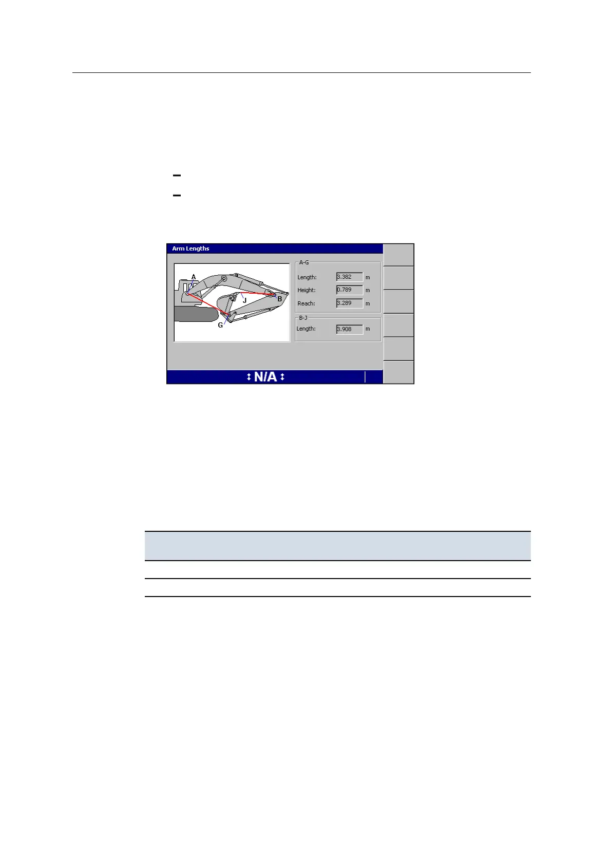
1. Use a tape to measure the following distances:
Boom pin to the bucket pin (A–G)
Stick pin to the end of the bucket teeth (B–J)
2. Compare your measurements with those that appear in the Diagnostics - Arm
Lengths dialog.
For more information, see A.15 Diagnostics.
C.6 Checking device connections
Use the Diagnostics dialogs to confirm that every connected device is visible and
working correctly.
If a device is not found, check that the device has power, then check if there is
continuity between:
This pin on the control box ... And this pin of the cable connector for the missing
component ...
K (CAN0 Hi) C
J (CAN0 Lo) D
For more information about the Diagnostics dialogs, refer to the GCS900 Grade
Control System for Excavators Operator's Manual and GCS900 Grade Control
System Site Supervisor’s Manual.
If the device is receiving power, but not found by the system, check the CAN bus.
For more information, see C.9 No CAN bus connection.
166 GCS900 GradeControl System for Excavators Installation Manual