9 2D system measurements
9.13 Arm sensor connections
When you set the arm sensor connections, you must connect only one arm sensor at
a time to the harness. For this reason it is easier to set the arm sensor connections
when you bench test the system.
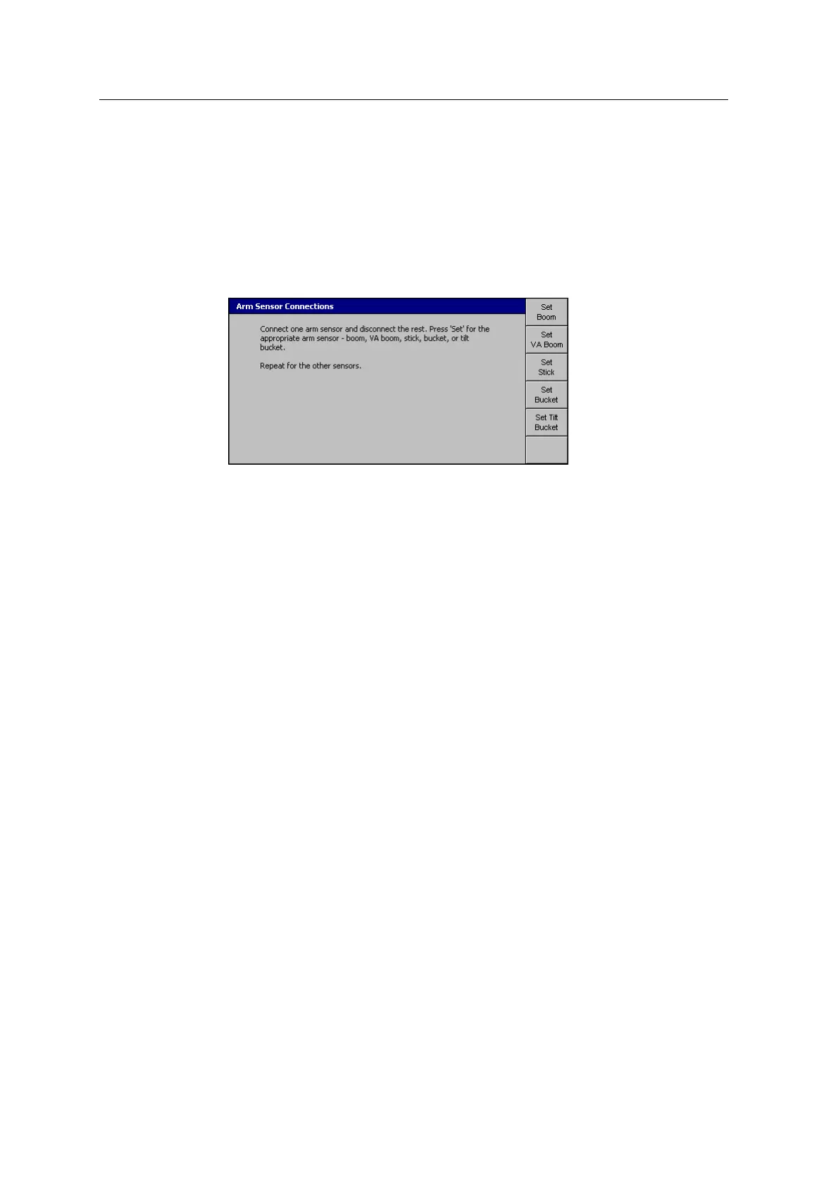
1. From Setup Menu – Installation, select Arm Sensor Connections:
2. Follow the on-screen instructions.
3.
Once you have set all of the connections, press =.
Note – After you set the connection for a sensor, label the sensor with it's
physical location on the arm.
Note – If you remove an angle sensor from the machine, you must remount the
sensor on the same arm segment for which it was originally configured.
Otherwise, you must reconfigure all of the sensors on the arm.
Note – If you set a tilt bucket, it will not appear in any other configuration and
calibration dialogs until you have created a tilt bucket. For more information,
see 9.12 Create bucket.
114 GCS900 GradeControl System for Excavators Installation Manual