6 Welding andFitting Tasks
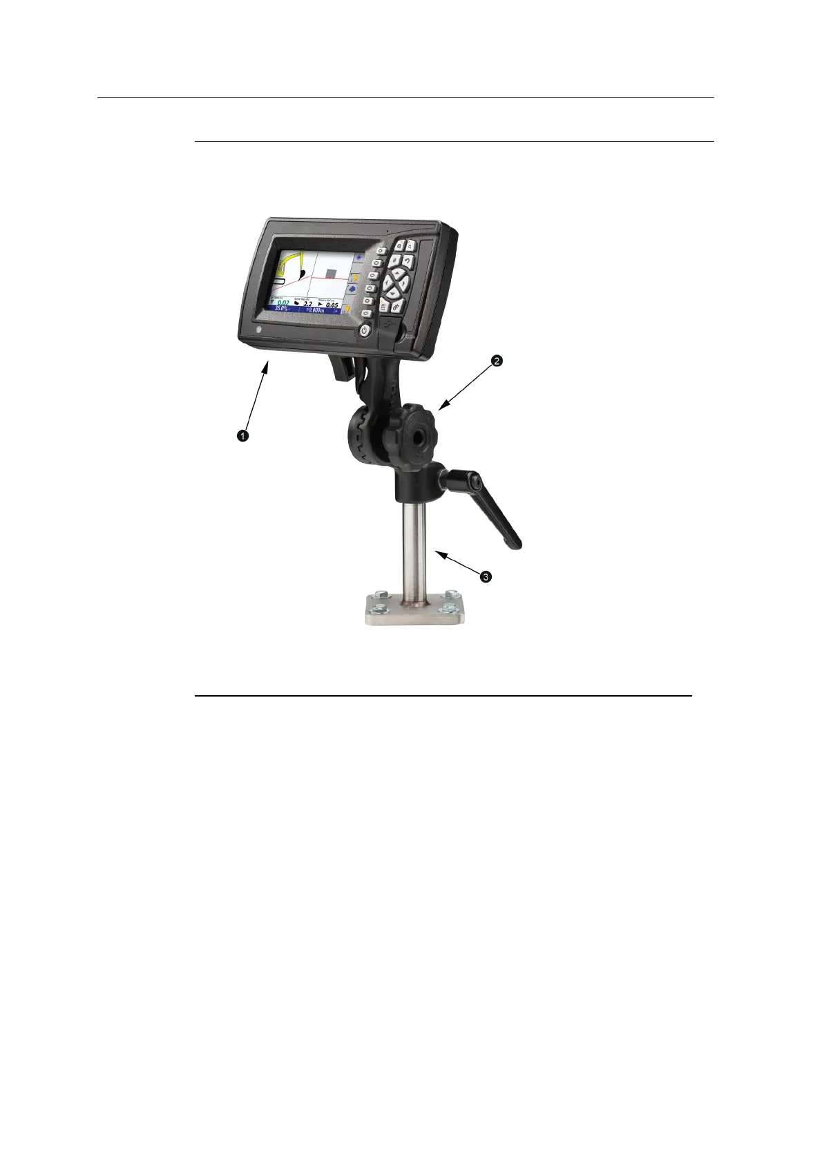
1
Control box
2
RAMmount
3
Pole bracket
Figure 6.6 Generic control box mount (RAM mount and control box installed)
Use the M10x40 screws, washers, split lock washers and nut plate or hex nuts to
attach the bottom plate of the mount to the cab.
6.12.2 Custom mount
If the mount supplied with the control box assembly is not suitable, you can modify
it or make your own.
If you do make a custom pole bracket, make sure that the diameter of the pole fits
the RAM mount properly. For example, use solid rod with an outer diameter of
8.5mm (
1
/
3
in) narrowing to 6.25mm (
1
/
4
in).
In this case the mount is bolted to the door pillar.
62 GCS900 Grade Control System for Excavators Installation Manual