8 Installing Fixed Sensor Components
8.4 Cab rotation sensor
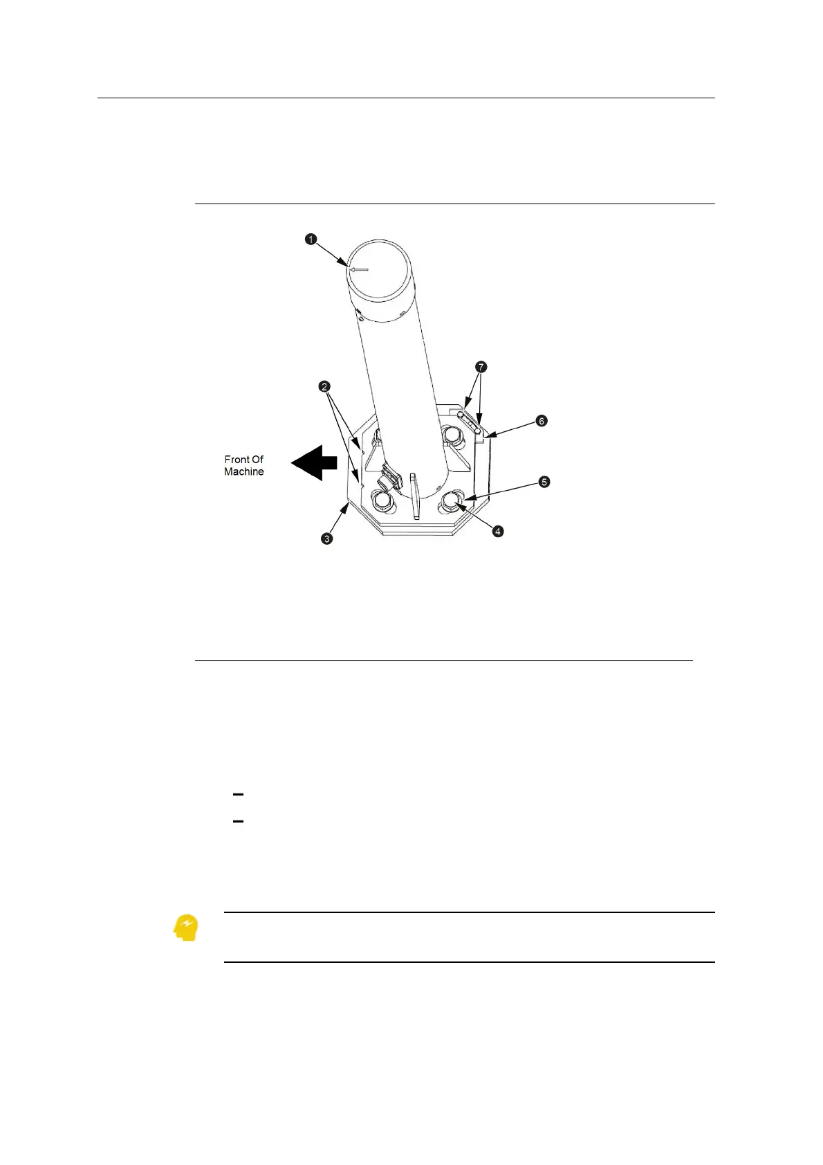
1
Forward arrow on top of
sensor
2
Notches on forward edge
of sensor base plate
3
Sensor bracket (welded
to counterweight)
4
M16 bolt
5
M16 washer
6
Locator plate
7
M5 allen head screws
Figure 8.1 Cab rotation sensor installation
1.1. Check the installation of the sensor bracket.
2. Apply the provided Loctite to the M16 bolts (4).
3. Loosely bolt the sensor to the mounting bracket using the M16 bolts (4) and
the washers (5) provided. The sensor must be installed so that:
the arrow on top of the sensor (1) points towards the front of the machine
the notches on the bottom plate of the sensor (2) are on the forward edge
of the bottom plate
4. Adjust the sensor so that the arrow (1) is parallel to the centerline of the
excavator body.
ATTENTION — If the body pitch/roll sensor feature of the HS410 heading sensor is
used, the alignment of the sensor with the centerline of the machine is critical.
80 GCS900 Grade Control System for Excavators Installation Manual