10 3D System Measurements
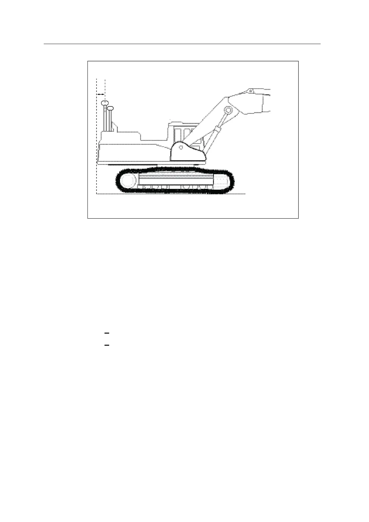
Note – If you have a dual GNSS system, measure from the back of the machine, to
the GNSS receiver that is closest to the back of the machine.
10.4.3 Body Vector Measurements
The pages that appear in the Body Vector Measurements wizards vary according to
the type of system you have.
To ensure that the system provides accurate guidance, you must:
l complete all of the on-screen instructions in the wizard. Take accurate
measurements; this is critical to system accuracy. For more information on
techniques, see:
10.2 GPS receiver over bucket / boom pin
10.3 Pole height with pole adaptor
l at the end of the process, reconnect the sensor harness cable to the system to
terminate the CAN bus.
Before you take the body vector measurements, you must calibrate the body
sensors, and also:
l install and configure the GNSS receivers or UTS instrument
l enter the Arm/Body measurements
132 GCS900 GradeControl System for Excavators Installation Manual