3D System Measurements 10
ATTENTION — A GNSSreceiver configuration file is loaded when a design file is loaded. If a
design file has not been loaded, then follow the procedure in A.11 GNSS receiver
configuration to load the .cfg file.
Note – After completion of the single GNSS/ UTS body vector measurements you
will have the option to use the automatically calculated boom pin lateral and reach
offsets, required for the 3D excavator guidance. See 9.11.1 Arm/Body
Measurements, section Machine body - Boom pin lateral and reach offsets.
The following process is for a single UTS system. The pages that appear for a
single or dual GNSS system are similar.
ATTENTION — Do not move the machine tracks at any stage during this process.
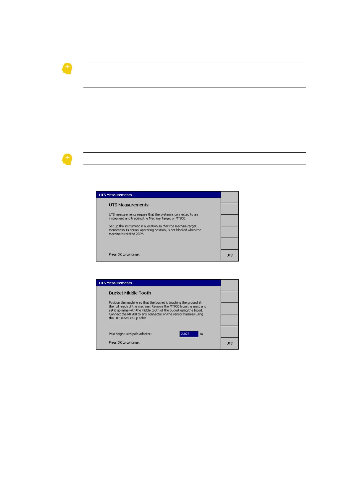
1. From Machine Dimensions, select Body Vector Measurements. A page similar
to the following appears:
2.
Follow the on-screen instructions and press \.
3. Check the Pole height with pole adaptor measurement.
Note – This measurement is critical to system accuracy. Do not take it for
granted that the default value is correct.
4.
Press \.
If the UTS is not tracking a target, a warning message appears. To reacquire
the target, see Resolving the UTS measurements warning message, page 136.
GCS900 Grade Control System for Excavators Installation Manual 133