10 3D System Measurements
5.
When the target has been acquired, press \. The UTS Measurements –
Bucket Middle Tooth page appears.
6.
Press \. A Measuring page appears.
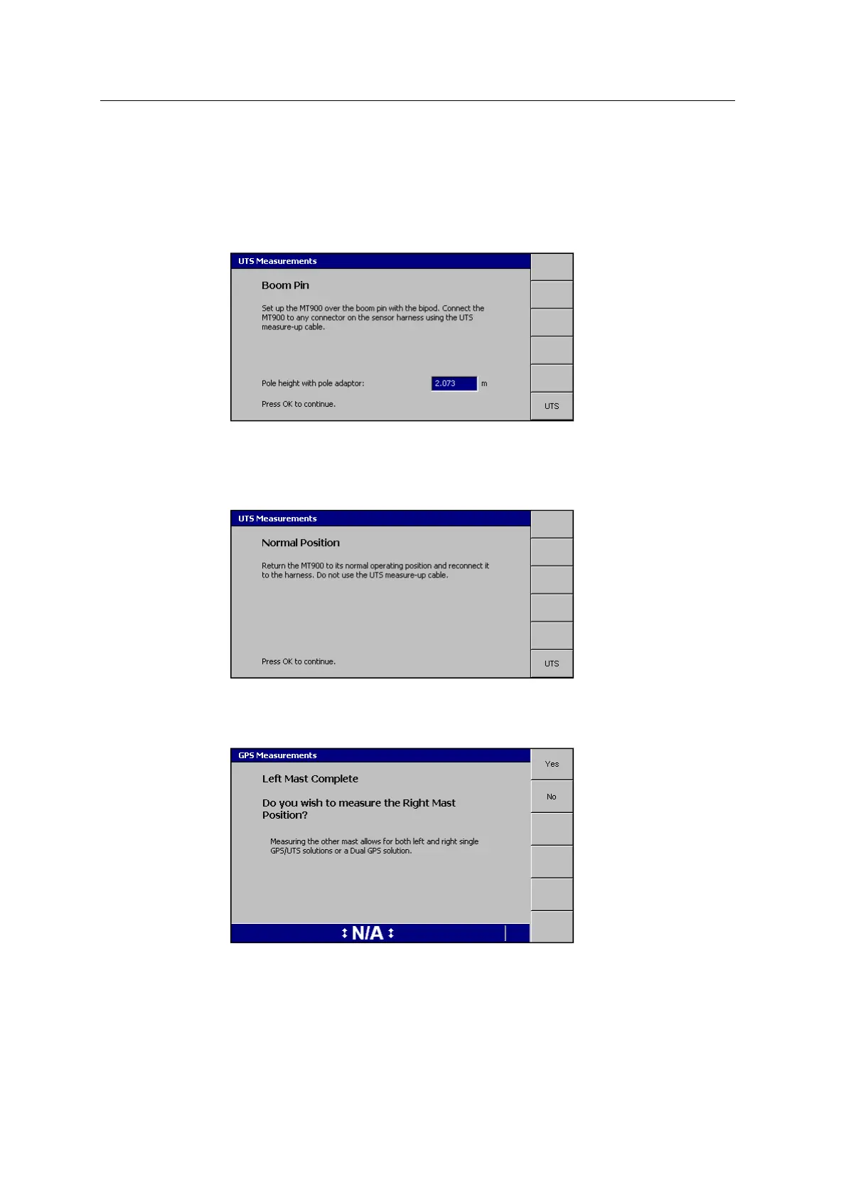
7. When the measurements are complete, the Boom Pin page appears:
8. Check the Pole height with pole adaptor measurement and edit if required.
9.
Press \. The Measuring page appears, followed by the Normal Position
page:
10.
Follow the on-screen instructions and press \.
The Measuring page appears, followed by the Left Mast Complete page:
Note – The option to measure the other mast is only available when the system
is configured as either 1xGNSS or UTS at the time of the measure-up.
134 GCS900 GradeControl System for Excavators Installation Manual