7 Installing theCab Components
wired to conform to the following pin-out:
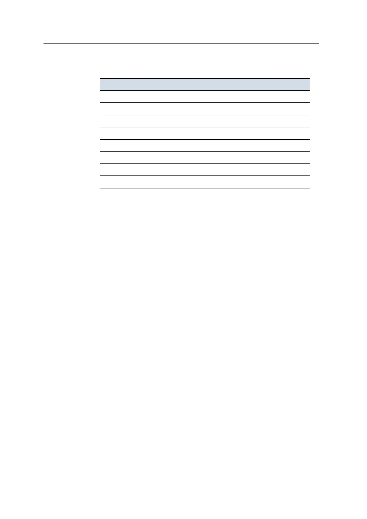
Pin
1
Function
1 PWR+
2 GND
3 RS-232: TXD (radio or modem)
5 ETHTXD+
6 ETHTXD-
7 ETH RXD+
8 ETH RXD-
10 RS-232: RXD (radio or modem)
1. All other pins are unused.
1. Connect the custom third-party cable to the radio.
2. Plug the 12-pin Deutsch connector on the custom third-party cable into the
standard 12-socket radio connector (DATARADIO) on the main harness.
For information on how to configure a third-party radio, see A.10 Control box’s
radio port.
Installing and connecting third party cellular modems
Mount the cellular modem inside the cab of your machine. For installation
instructions, refer to the manufacturer's documentation.
Mixed wireless (cellular modem and data radio) connection
This configuration allows the system to receive GNSS corrections from a local base
station, or position information from a UTS, and to connect to the Connected
Community website.
For installation instructions, refer to the manufacturer's documentation.
7.4.2 SNRxxx data radio
Optionally, you can install both an SNRxxx data radio and an SNM940 cellular
modem. This section describes the installation options for both modems.
72 GCS900 Grade Control System for Excavators Installation Manual