C Validation andTroubleshooting
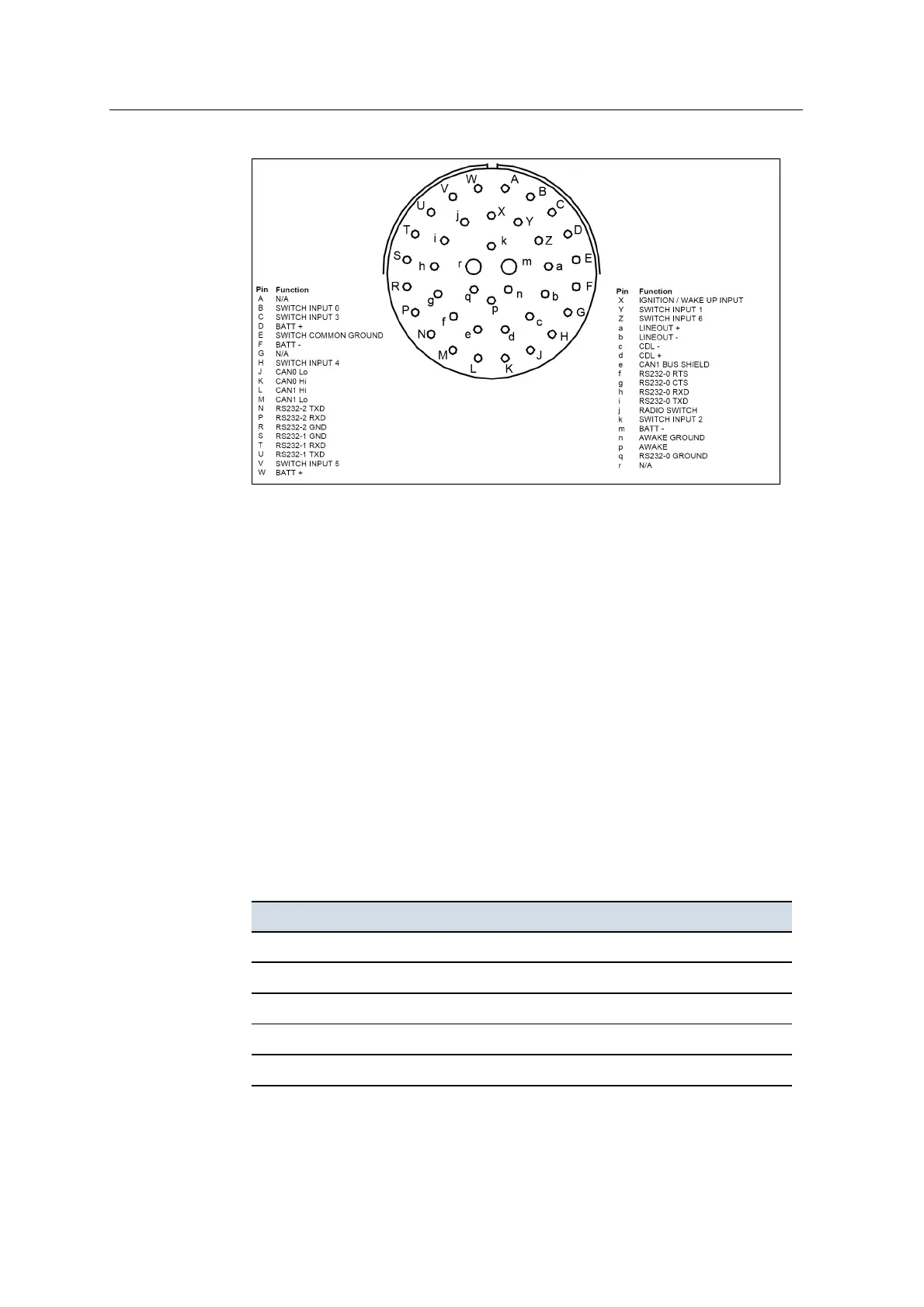
Figure C.1 Control box – power/data connector
C.9 No CAN bus connection
Note – There are two independent CAN buses on the system.
If there appears to be no CAN bus communication, complete the following:
Check the terminators:
1. Connect all the system components to the harness and remove power from the
system.
2. Check that all CAN terminators are correctly installed on the machine harness.
3. Disconnect the system harness from the device.
4. Use a multimeter to check that the impedance of each CAN bus is
approximately 60Ω resistance at any connector.
5.
Check that the resistance between CAN0 Hi and CAN0 Lo is 60Ω±20% on
the following:
Device CAN0 Hi CAN0 Lo
Data radio 4 5
MT900 machine target C D
GNSS receiver P L
HS410 cab rotation sensor C D
AS45x angle sensor C D
168 GCS900 GradeControl System for Excavators Installation Manual