SetupMenus A
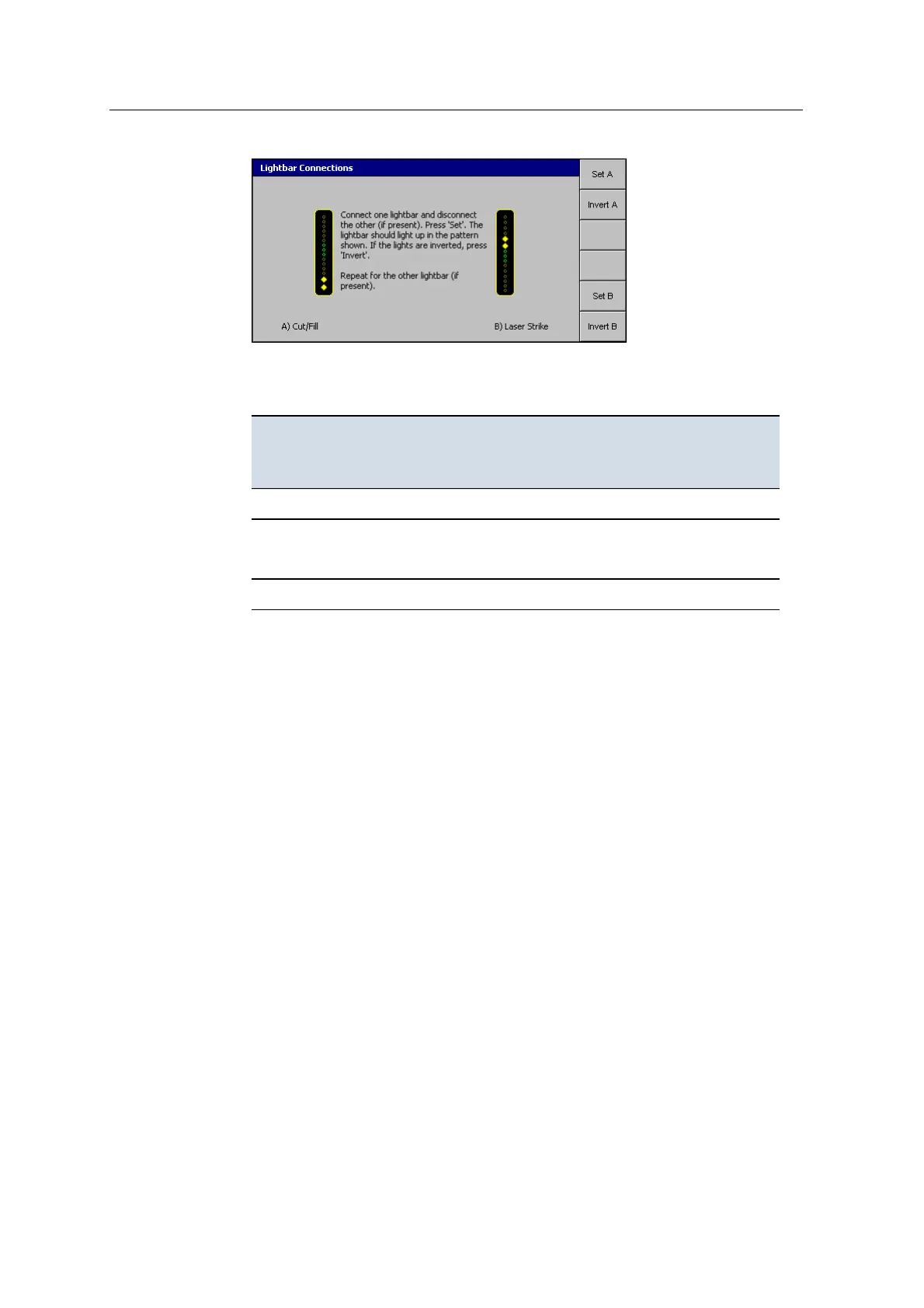
2. Check the LED pattern on the lightbars to see if they correspond to the dialog.
If they do not, for each lightbar that is wrong, do the following:
For this on-screen
lightbar ...
Connect this lightbar
to the harness
(disconnect others) ...
Then
press this
softkey ...
If the LEDs light up at
the wrong end, then
press this softkey ...
Cut/Fill Left
Set A Invert A
Left/Right
Laser Strike
Center
Set B Invert B
Forward/Back Right
Set C Invert C
3.
Press \.
Note – After removal, return each lightbar to the same position. Otherwise,
you will need to reset the Lightbar Connections.
For more information, refer to the GCS900 Grade Control System for Excavators
Operator's Manual.
A.7 Select radio band
The SNRxxx /SNRx20 radio modem can support more than one frequency mode.
You must set the required frequency prior to operating the system.
GCS900 Grade Control System for Excavators Installation Manual 145