Installing theMain Harness Assembly 5
1
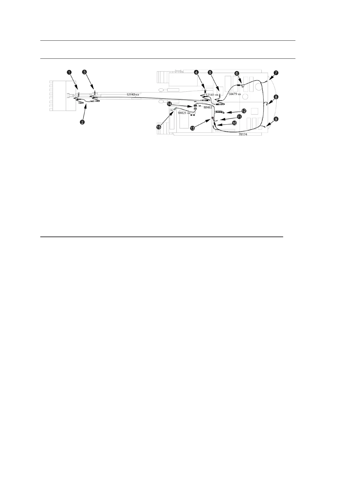
Bucket angle sensor
connector
2
Bucket harness
3
Stick angle sensor connector
4
Boom angle sensor connector
5
Body angle sensor connector
6
Front body harness connector
on rear body harness (BOOM
HARNESS)
7
Right GNSS connector
(RIGHTGNSS)
8
Rotation sensor connector
(AUXILIARY)
9
Left GNSS/UTS target
connector(LEFTGPS)
a
Cab harness connector on
rear body harness (CAB
HARNESS)
b
Power connector (POWER)
c
Diagnostic port
(DIAGNOSTICS)
d
Data radio connector (DATA
RADIO)
e
Cab harness bulkhead
connector (USER
INTERFACE)
f
Control box connector
(DISPLAY)
Figure 5.1 Excavator main harness assembly
5.4.1 Install the arm harness
Connect the following cables together:
l The bucket harness
l The stick harness
l The boom harness
Loosely cable tie the bucket angle sensor connector to the dogbone (idler link).
Progress up the stick, continuing to loosely secure the bucket harness to the rigid
hydraulic lines. At the top of the stick, loosely secure the stick angle sensor
connector, and then follow the flexible hydraulic hoses across the stick / boom joint.
Run the stick harness along the top of the boom, loosely securing the cable to the
rigid hydraulic lines. Loosely secure the boom angle sensor connector about 50 cm
(20 inches) above the boom pin, and then follow the flexible hydraulic hoses across
the boom pin into the body of the machine.
GCS900 Grade Control System for Excavators Installation Manual 37