Installing theCab Components 7
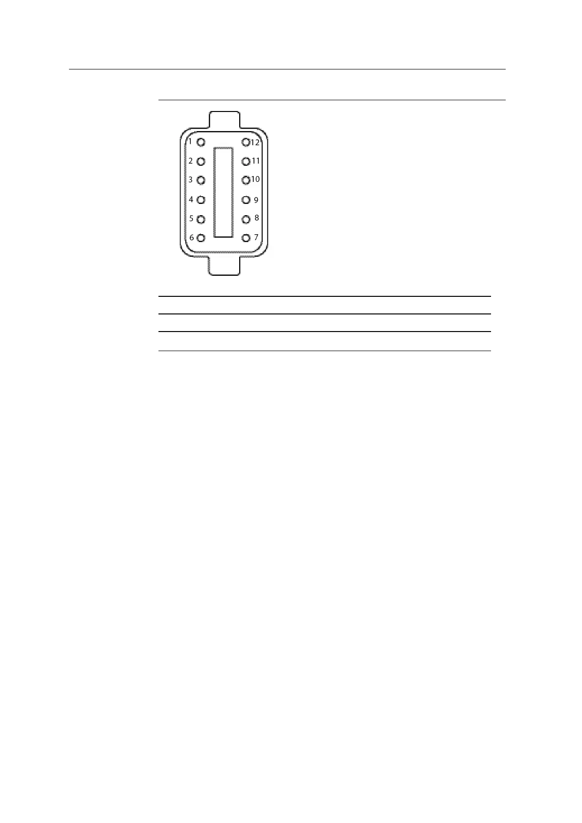
1 = Blue 2 = Purple 3 = Brown/White
4 = Brown 5 = White 6 = Yellow
Note — All other pins are unused.
Figure 7.2 Connecting the standard excavator remote switch assembly (Deutsch
12-pin plug rear view)
8. Route and secure the remote switch cable (P/N57545-xx).
9. Connect the newly formed Deutsch 12-pin receptacle to Deutsch 12-socket
connector on the remote switch cable.
10. Connect the Deutsch 8-pin receptacle on the remote switch cable to the 8-
socket connector on the display harness (P/N94021-xx).
7.6 Lightbars
Note – External lightbars are only available for systems that include a CB460
control box.
To attach the lightbar directly to a suitable surface in the cab, use one of the
following:
l The supplied nuts, washers, and bolts
l Double-sided tape
l Hook and loop tape
GCS900 Grade Control System for Excavators Installation Manual 75