Welding andFitting Tasks 6
6.7.1 Select a location for the bucket cable clamp bracket
When you run the armored cable from the harness connector to the bucket, follow
the existing hydraulic hoses.
1. Connect the sensor to the harness cable.
2. Assemble the cable clamp around the section of the armored cable closest to
the female socket.
3. Rotate the cable clamp until the mounting bracket is flush against the bucket.
4. Move the cable clamp until you take up nearly all of the slack in the cable.
5. Ensure that the cable clamp is parallel to the closest edge of the sensor.
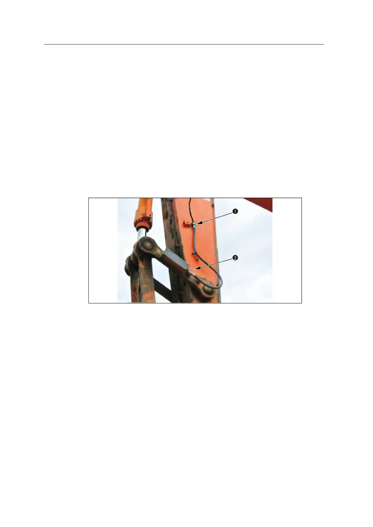
The following image shows an armored bucket angle sensor cable installed using
two cable clamps (1 and 2).
6.7.2 Install the bucket cable clamp bracket
Weld the cable clamp brackets to the stick or the bucket angle sensor mounting
component.
6.8 Stick and boom angle sensor brackets
The AS450/LC450 stick and boom angle sensor brackets can be welded directly to
the arm or bolted to weld bosses using the bolt holes (1) on either the vertical or
horizontal faces, however for ease of maintenance the brackets are typically bolted
to weld plates. The sensor is secured to the bracket using the studs (2) and aligned
by the locating pins (3).
GCS900 Grade Control System for Excavators Installation Manual 49