6 Welding andFitting Tasks
6.5.1 Select a location for the tilt bucket cable clamp bracket
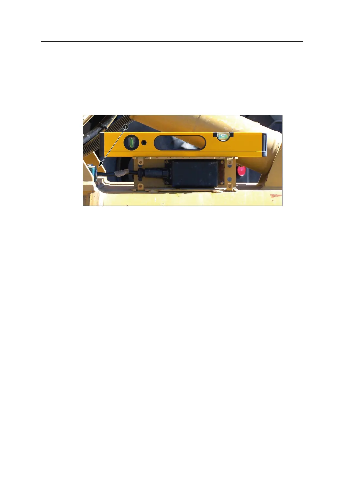
The following image shows an armored tilt bucket angle sensor cable installed using
a cable clamp (1). The tilt bucket sensor cable clamp positions are determined by
temporarily assembling an armored cable onto the tilt bucket sensor mount and then
using the cable to layout the clamp positions.
6.5.2 Install the bucket cable clamp bracket
Weld the cable clamp brackets to the stick and the tilt bucket angle sensor mounting
component.
6.6 Bucket angle sensor bracket
The AS450 bucket angle sensor brackets can be welded directly to the machine or
bolted to a plate or weld bosses using the bolt holes (1) on the horizontal face. The
sensor is secured to the bracket using the studs (2) and aligned by the locating pins
(3).
46 GCS900 Grade Control System for Excavators Installation Manual