2D system measurements 9
Bucket sensor mounted on the Idler Arm/Dogbone configuration
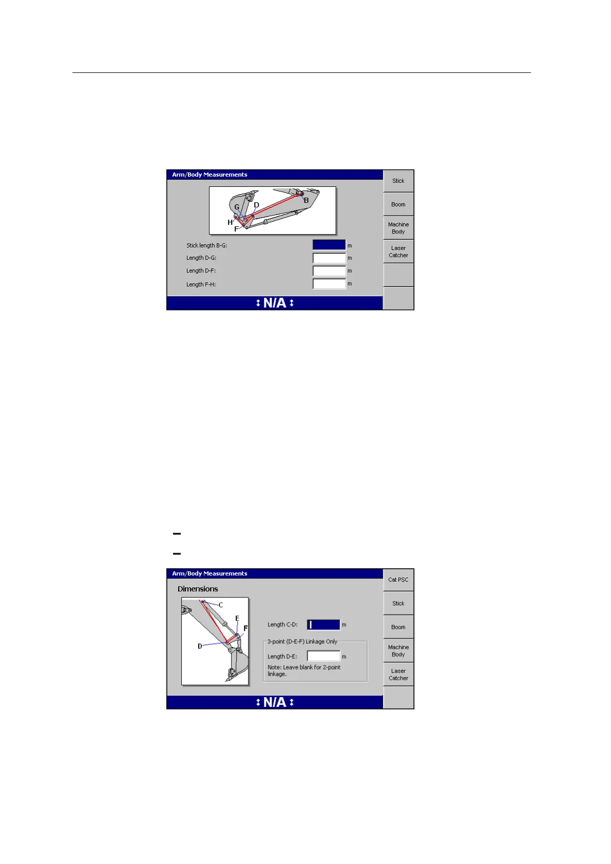
1. The first page of the Arm Body Measurements dialog is for the stick
measurements:
2. Enter your stick measurements into the dialog.
3. Enter the machine measurements for each softkey.
Note – The VA Boom and Laser Catcher softkeys only appear when you have
configured your system for a VA boom and/or laser catcher.
Note – For machines with a VA boom, the ‘Boom measurements’ page changes
to reflect the required measurements.
4.
Press \.
Cat PSC configuration
1. The first page of the Arm Body Measurements dialog is for Cat PSC
dimensions. When a machine is configured with Cat bucket PSCsupport, the
following dimensions are necessary:
Length C-D
Length D-E, for 3 point idler arm linkage only
GCS900 Grade Control System for Excavators Installation Manual 107