9 2D system measurements
Note – There is no need to determine the 3 point idler arm angle EDF. This
angle is assumed a constant, calculated when the bucket is created.
2. Enter your measurements into the dialog.
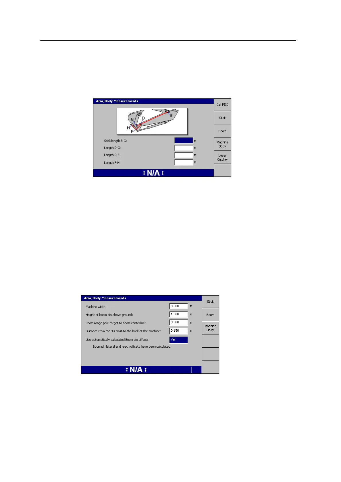
3. Press the Stick softkey and enter the stick measurements:
4. Enter the machine measurements for each softkey.
Note – The Laser Catcher softkey only appears when you have configured your
system for laser catcher.
5.
Press \.
Machine body - Boom pin lateral and reach offsets
For machines with displays that support 3D excavator guidance, this measurement
can be done automatically, by selecting "Yes" in the field "Use automatically
calculated Boom pin offsets", in the Machine Bodydialog.
If you have already completed the single GNSS/ UTS body vector measurements
(see 10.4.3 Body Vector Measurements), a page similar to the following appears:
If you have not yet completed the single GNSS/UTS body vector measurements, the
following screen appears:
108 GCS900 GradeControl System for Excavators Installation Manual