10 3D System Measurements
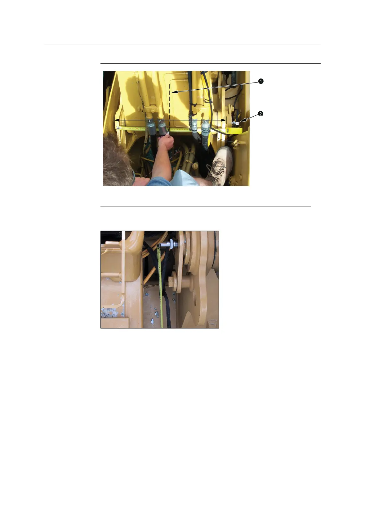
1
Boom centerline
2
Range pole target
2. Screw the boom center finder chuck into the boom pin. Insert the range pole
target into the chuck and connect the measuring tape to the range pole target:
3. Set up the range pole on the range pole target. For more information, see Figure
10.1.
4. Measure from the center of the range pole to the boom centerline:
130 GCS900 GradeControl System for Excavators Installation Manual