5-41
POWR
E
CRANKSHAFT AND PISTON/
CONNECTING ROD ASSEMBLY
Measuring steps
CAUTION:
Install the bearings in their original posi-
tions. Incorrect oil clearance measurements
can lead to engine damage.
(1) Clean the bearings, main journals, and
bearing portions of the crankcase and
cylinder block.
(2) Place the cylinder block upside down
on a bench.
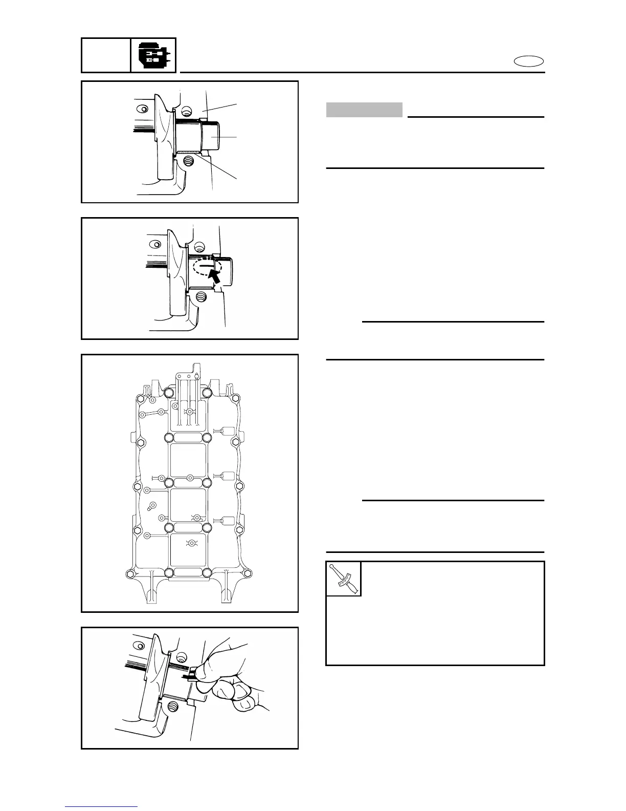
(3) Install half of the bearings 1 and the
crankshaft 2 into the cylinder block 3.
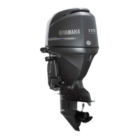
(4) Put a piece of Plastigauge
on each
main journal in parallel to the crank-
shaft.
NOTE:
Do not put the Plastigauge
over the oil
hole in the main journal of the crankshaft.
(5) Install the other half of the bearings
into the crankcase.
(6) Install the crankcase onto the cylinder
block.
(7) Apply engine oil on to the threads and
seat of the crankcase bolts.
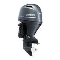
(8) Tighten the bolts to the specified
torque in two steps in the order shown
in the illustration.
NOTE:
Do not move the crankshaft until the main-
bearing oil clearance measurement has
been completed.
(9) Remove the crankcase.
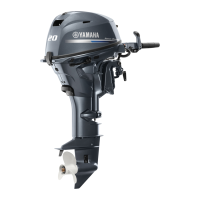
(10) Measure the width of the compressed
Plastigauge
on each main journal.
* Torque valve (for reference only)
T
R
.
.
Bolt (M8)
1st: 14 Nm (1.4 m • kgf, 10 ft • lb)
2nd: 28 Nm (2.8 m • kgf, 20 ft • lb)
Bolt (M10)
1st: 19 Nm (1.9 m • kgf, 14 ft • lb)
2nd: 60˚
50 Nm
(5.0 m • kgf, 36 ft • lb)*
2
3
1
5510
5520
I
E
A
D
H
8
7
G
C
B
3
4
1
KL
2
5
6
F
J
0
9
5530
5540


 To Next Page