4.5 I/O Signal Connections
4.5.1 I/O Signal Connector (CN1)
4-35
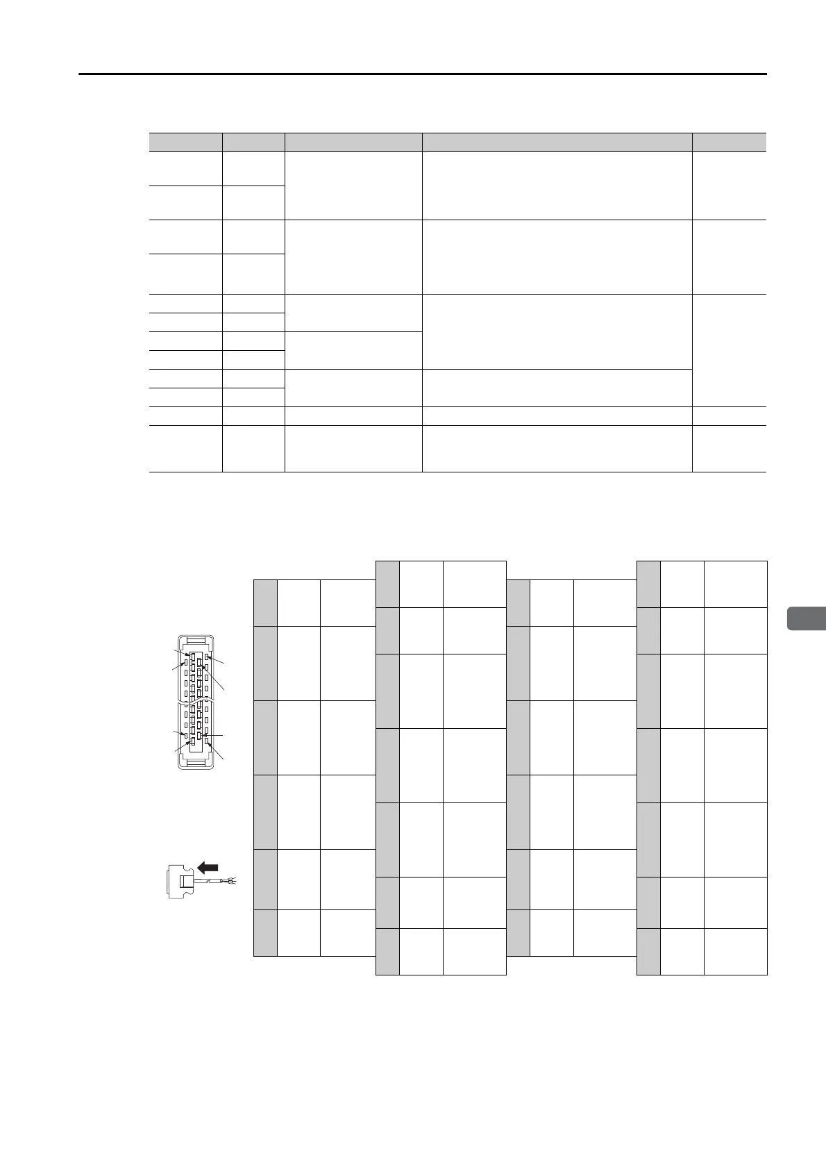
Pin Layout
The following figure gives the pin arrangement of the of the I/O signal connector (CN1) for the
default settings.
/SO2+
(/BK+)
23
Brake Output
You can allocate the output signal to use with
a parameter.
(Controls the brake. The brake is released
when the signal turns ON (closes).)
page 6-8
/SO2-
(/BK-)
24
/SO3+
(/S-RDY+)
25
Servo Ready Output
You can allocate the output signal to use with
a parameter.
(Turns ON (closes) when the SERVOPACK is
ready to acknowledge the /S-ON (Servo ON)
signal.)
page 6-8
/SO3-
(/S-RDY-)
26
PAO 17
Encoder Divided Pulse
Output, Phase A
Output the encoder divided pulse output sig-
nals with a 90° phase differential.
page 6-23
page 6-29
/PAO 18
PBO 19
Encoder Divided Pulse
Output, Phase B
/PBO 20
PCO 21
Encoder Divided Pulse
Output, Phase C
Outputs the origin signal once every encoder
rotation.
/PCO 22
SG 16 Signal ground This is the 0-V signal for the control circuits. −
FG Shell Frame ground
Connected to the frame ground if the shield of
the I/O Signal Cable is connected to the con-
nector shell.
−
The above view is
from the direction
of the following
arrow without the
connector shell
attached.
1
/SO1+
(/WARN+)
Warning
Output
14 BAT+
Battery for
Absolute
Encoder (+)
2
/SO1-
(/WARN-)
Warning
Output
15 BAT-
Battery for
Absolute
Encoder (-)
3ALM+
Servo
Alarm
Output
16 SG
Signal
Ground
4ALM-
Servo
Alarm
Output
17 PAO
Encoder
Divided
Pulse
Output,
Phase A
5TH
Overheat
Protection
Input
18 /PAO
Encoder
Divided
Pulse
Output,
Phase A
6 +24VIN
Sequence
Input Sig-
nal Power
Supply
Input
19 PBO
Encoder
Divided
Pulse
Output,
Phase B
7
/ALM-
RST
Alarm
Reset Input
20 /PBO
Encoder
Divided
Pulse
Output,
Phase B
8P-OT
Forward
Drive
Prohibit
Input
21 PCO
Encoder
Divided
Pulse
Output,
Phase C
9N-OT
Reverse
Drive
Prohibit
Input
22 /PCO
Encoder
Divided
Pulse
Output,
Phase C
10 /DEC
Homing
Decelera-
tion Switch
Input
23
/SO2+
(/BK+)
Brake
Output
11
Not
used
−
24
/SO2-
(/BK-)
Brake
Output
12 /RGRT
Registra-
tion Input
25
/SO3+
(/S-
RDY+)
Servo
Ready
Output
13 /S-ON
Servo ON
Input
26
/SO3-
(/S-
RDY-)
Servo
Ready
Output
Continued from previous page.
Signal Pin No. Name Function Reference
Pin 15
Pin 1
Pin 2
Pin 12
Pin 13
Pin 26
Pin 25
Pin 14

 Loading...


