Routing elements
138
System functions and features as of R3.0
syd-0367/1.3 – R3.0 – 03.2013
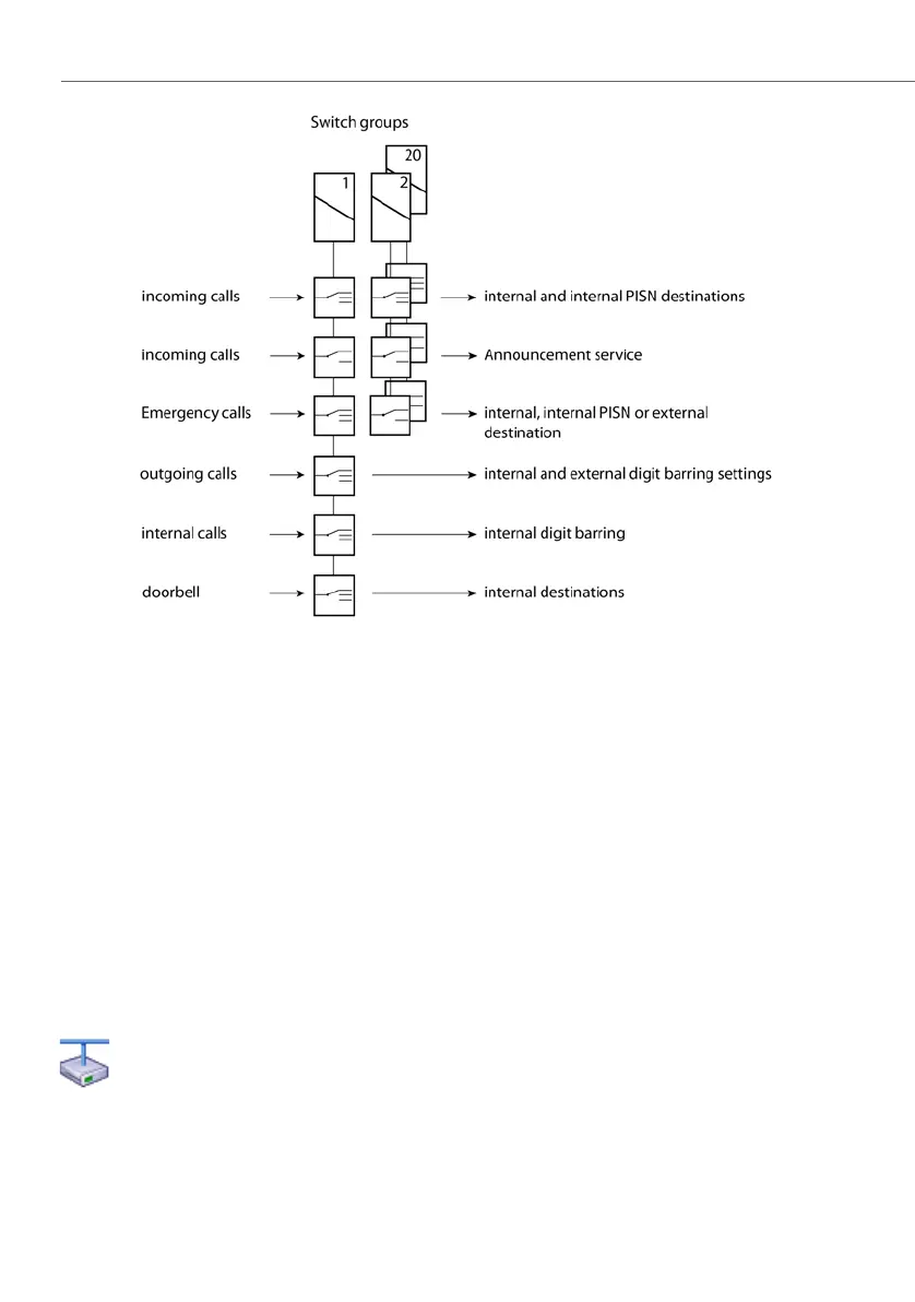
Fig. 57 Switch groups and how their changeover switches are used
The choice of switch group and the assignment of the switch positions are carried
out in the appropriate menus of the system configuration. After initialization the
changeover switches are allocated throughout to switch group 1.
Switch groups are selected via menu selection or by dialling */# function codes on
a terminal (see "Switching switch groups", page 522). The relevant authorization
can be regulated individually for each internal user. (Operate switch group setting).
Digit barrings can also be used to limit authorizations to individual switch groups.
The switch groups can also be switched over via FXS interfaces configured as con-
trol inputs or via the control inputs of an ODAB options card (Aastra 415/430). The
switch group configuration determines which of the switch groups 1…20 are
switched. Selection via the control inputs takes precedence over selection via */#
function codes. This means that the */# function codes cannot be executed as long
as a signal is imposed at the control inputs.
Aastra Intelligent Net:
In an AIN the control inputs can be used as a mix of FXS interfaces and
ODAB options cards (Aastra 415/430). The maximum number of cards per
communication server has to be taken into account. The switch group
configuration determines which options card switches what switch
group. The following rules apply:
 Loading...


