Routing elements
169
System functions and features as of R3.0
syd-0367/1.3 – R3.0 – 03.2013
5. 11. 4. 1 Application Examples for Key Telephones
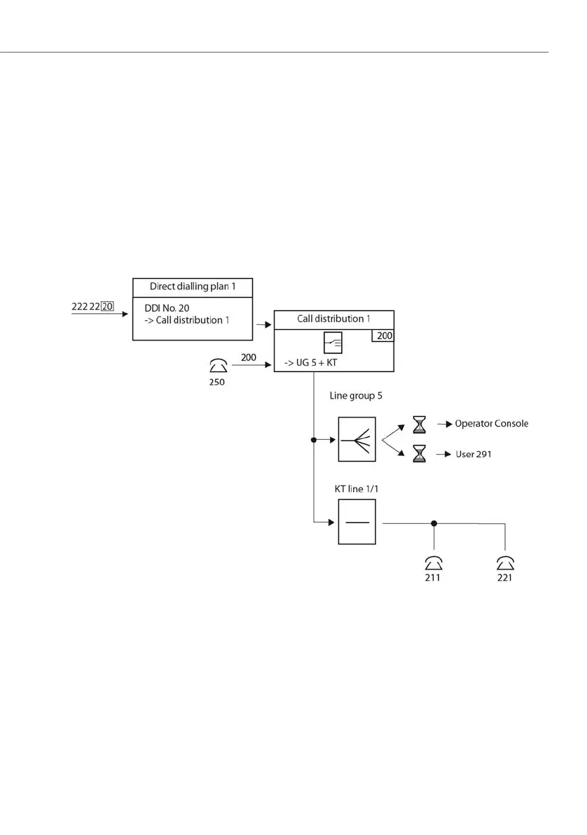
Destination Combination KT+UG
The combined destination KT line and user group 5 has been configured in call dis-
tribution element 1 with number 200 in the numbering plan.
Two line keys are connected to the KT line 1/1 It is therefore a through KT line The
first line key belongs to the key telephone with user number 211; the second be-
longs to the key telephone with user number 221.
The element Operator console is configured on user group 5. Internal user 291 is en-
tered as member of the member group. Delay is activated for both elements (Oper-
ator console and user).
Fig. 69 Application for key telephones and user group
If an incoming call is not answered within the set delay time using the line keys of
users 211 or 221, the call will be routed on to user group 5 and signalled at the
same time to the operator console and user 291.
 Loading...


