R
X
Z3
Z2
Z1
Z4
Z5
ZRV
R
X
ZS=0
ZS=Z1
ZS=2Z1
IEC15000056-1-en.vsdx
IEC15000056 V1 EN-US
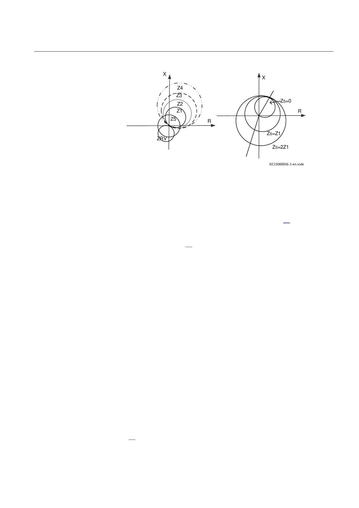
Figure 47: Mho, offset mho characteristics and the source impedance
influence on the mho characteristic
The mho characteristic has a dynamic expansion due to the source impedance.
Instead of crossing the origin, as for the mho to the left of figure
47, which is only
valid where the source impedance (Zs) is zero, the crossing point is moved to the
coordinates of the negative source impedance given an expansion of the circle
shown to the right of figure 47. Z1 denotes the complex positive sequence
impedance.
The magnitude of the polarizing voltage is determined completely by the positive
sequence voltage magnitude from before the fault. This will give a somewhat less
dynamic expansion of the mho circle during faults. However, if the source
impedance is high, the dynamic expansion of the mho circle might lower the
security of the function too much with high loading and mild power swing
conditions.
Basic operation characteristics
GUID-E6CC3CA7-72BE-40FC-A557-7BDB62F7BC1E v2
In ZMFPDIS, each zone measurement loop characteristic can be set to mho
characteristic or offset mho characteristic by setting OpModePEZx or
OpModePPZx (where x is 1-5 depending on selected zone).
ZMFPDIS fixes zone 1 and 2 in Forward mode and zone RV in Reverse mode.
Zone 3-5 can be set to Non-directional, Forward or Reverse by setting the
parameter DirModeZx (where x is 3-5 depending on selected zone).
If DirModeZx (where x is 3-5 depending on selected zone) is selected as Non-
directional, the directional element will not have any effect on the measurement
loop and operation of the function. When DirModeZx (where x is 3-5 depending on
selected zone) is selected as Forward or Reverse, directional lines are introduced.
Information about the directional lines is given from the directional element. Basic
Mho and offset Mho characteristics with different mode settings are indicated in
figure
48.
1MRK 505 394-UEN A Section 7
Impedance protection
Line differential protection RED650 2.2 IEC 125
Technical manual