calculation of the operation pulse sent in advance is using the measured
SlipFrequency and the set tBreaker time. To prevent incorrect closing pulses, a
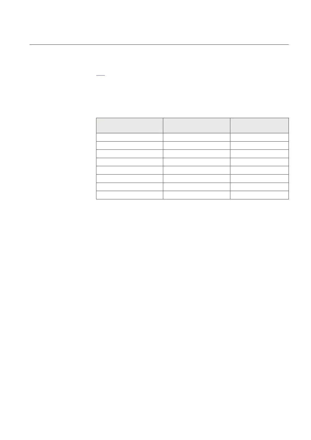
maximum closing angle between bus and line is set with CloseAngleMax. Table
169 below shows the maximum settable value for tBreaker when CloseAngleMax
is set to 15 or 30 degrees, at different allowed slip frequencies for synchronizing.
To minimize the moment stress when synchronizing near a power station, a
narrower limit for CloseAngleMax needs to be used.
Table 169: Dependencies between tBreaker and SlipFrequency with different CloseAngleMax
values
tBreaker
[s] (max settable value)
with
CloseAngleMax
= 15 degrees
[default value]
tBreaker
[s] (max settable value)
with
CloseAngleMax
= 30 degrees
[max value]
SlipFrequency [Hz]
(BusFrequency -
LineFrequency)
0.040
0.080 1.000
0.050 0.100 0.800
0.080 0.160 0.500
0.200 0.400 0.200
0.400 0.810 0.100
1.000 0.080
0.800 0.050
1.000 0.040
At operation the SYNOK output will be activated with a pulse tClosePulse and the
function resets. The function will also reset if the synchronizing conditions are not
fulfilled within the set tMaxSynch time. This prevents that the function is, by
mistake, maintained in operation for a long time, waiting for conditions to be
fulfilled.
The inputs BLOCK and BLKSYNCH are available for total block of the complete
SESRSYN function and block of the Synchronizing function respectively.
TSTSYNCH will allow testing of the function where the fulfilled conditions are
connected to a separate output.
1MRK 505 394-UEN A Section 12
Control
Line differential protection RED650 2.2 IEC 311
Technical manual