a>b
a
b
Counter
Rst
CU
CV
X
q
-1
÷
÷
R I
R I
a>b
a
b
0
Counter
Rst
CU
CV
q
-1
EAFPULSE
RSTACC
EAFACC
T
F
t
tOff
TP
0
q
-1
tEnergyOffPls
1000 GWh
EAFAccPlsQty
tEnergyOnPls
q
-1
= unit delay
IEC13000188-5-en.vsdx
IEC13000188 V5 EN-US
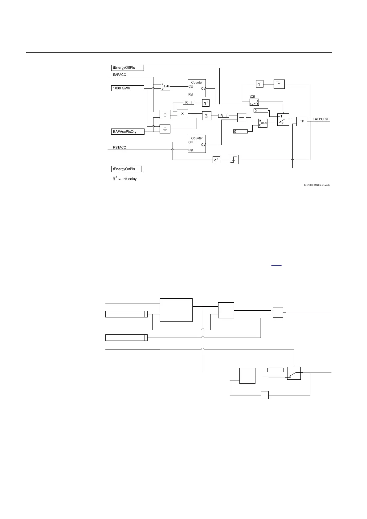
Figure 307: Logic for pulse generation of integrated active forward energy
The maximum demand values for active and reactive power are calculated for the
set time interval tEnergy. The maximum values are updated every minute and
stored in a register available over communication and from outputs MAXPAFD,
MAXPARD, MAXPRFD and MAXPRRD for the active and reactive power forward
and reverse direction. When the RSTDMD input is active from the local HMI reset
menu, these outputs are reset to zero. The energy alarm is activated once the
periodic energy value crosses the energy limit ExLim. Figure 308 shows the logic
of alarm for active forward energy exceeds limit and Maximum forward active
power demand value. Similarly, the maximum power calculation and energy alarm
outputs in the active reverse, reactive forward and reactive reverse is implemented.
Average Power
Calculation
X
a>b
a
b
q
-1
T
F
0.0
tEnergy
EALim
P (ACTIVE FORWARD)
RSTMAXD
EAFALM
MAXPAFD
MAX
IEC13000189-4-en.vsd
q
-1
= unit delay
IEC13000189 V4 EN-US
Figure 308: Logic for maximum power demand calculation and energy alarm
Section 16 1MRK 505 394-UEN A
Metering
620 Line differential protection RED650 2.2 IEC
Technical manual