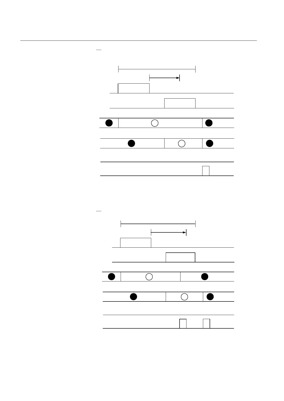
Figure 25 shows the timing diagram when a new indication appears after the first
one has reset but before tRestart has elapsed.
IEC01000241_2_en.vsd
Activating
signal 2
LED 2
Manual
reset
Activating
signal 1
Automatic
reset
LED 1
Disturbance
tRestart
IEC01000241 V2 EN-US
Figure 25: Operating sequence 6 (LatchedReset-S), two indications within
same disturbance but with reset of activating signal between
Figure 26 shows the timing diagram for manual reset.
IEC01000242_2_en.vsd
Activating
signal 2
LED 2
Manual
reset
Activating
signal 1
Automatic
reset
LED 1
Disturbance
tRestart
IEC01000242 V2 EN-US
Figure 26: Operating sequence 6 (LatchedReset-S), manual reset
Section 5 1MRK 505 394-UEN A
Local Human-Machine-Interface LHMI
82 Line differential protection RED650 2.2 IEC
Technical manual