58 Chapter 3
Front/Rear Panel and LCD Display
Items Displayed on the LCD
V ¯ Indicates that, because you specified dc voltage bias (in constant
voltage mode) with a setting that exceeds the defined voltage limit, the
actual applied voltage differs from the intended setting.
I ¯ Indicates that, because you specified dc current bias (in constant
current mode) with a setting that exceeds the defined current limit, the
actual applied current differs from the intended setting.
(blank) Indicates that dc bias conditions are not applied.
Note that when dc bias conditions are applied, the “DC BIAS ON” indicator appears in the
lower-right corner of the screen, regardless of which bias mode (DCB, VC, IC, V ¯, or I ¯)
is selected.
Adapter type
EX1 Indicates that the instrument is configured to use a 1-meter,
four-terminal pair cable.
EX2 Indicates that the instrument is configured to use a 2-meter,
four-terminal pair cable.
7mm Indicates that the instrument is configured to use the Agilent 42942A
Terminal Adapter (four-terminal pair to 7-mm conversion adapter).
PRB Indicates that the instrument is configured to use the 42941A
Impedance Probe.
(blank) Indicates that the instrument is configured to operate without an
adapter.
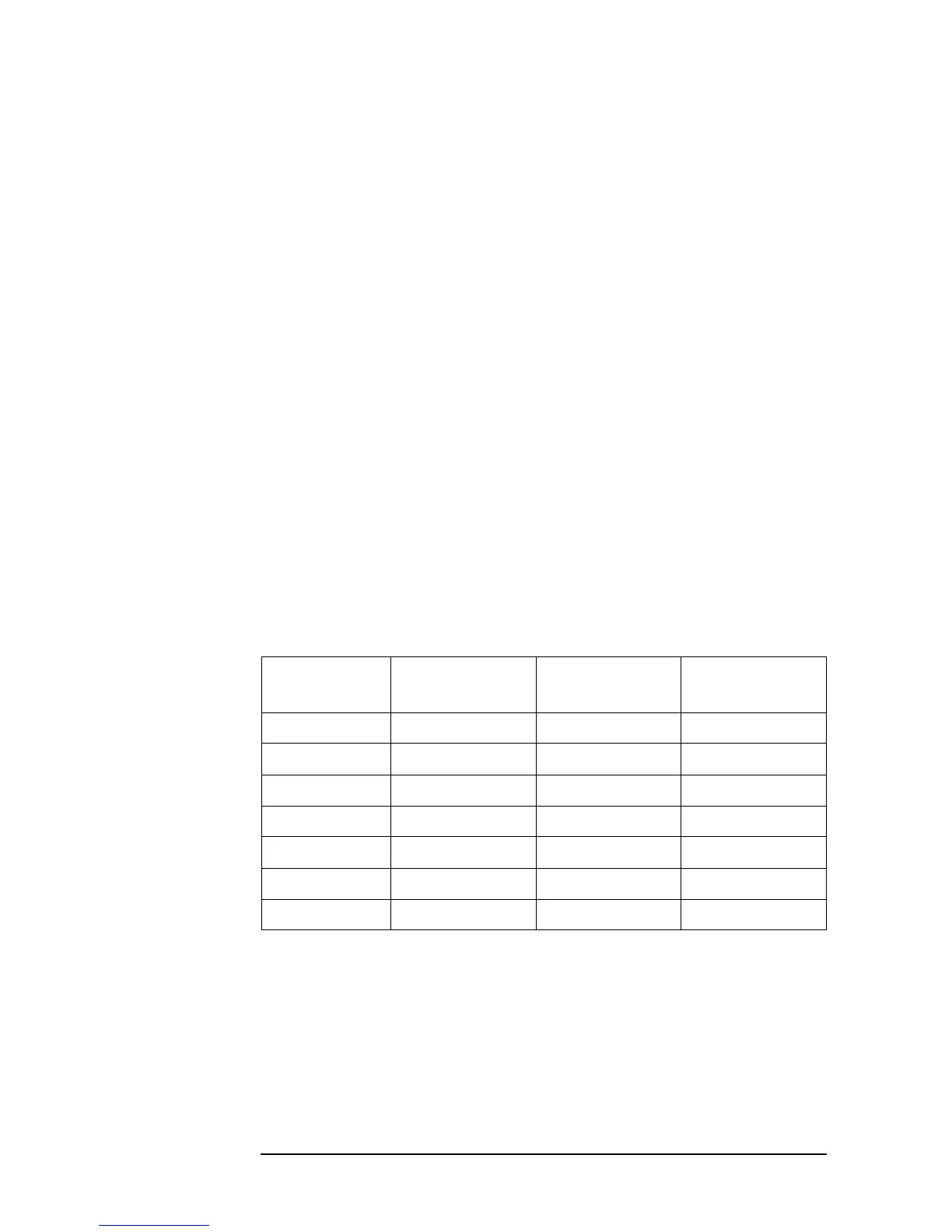
User calibration/port extension status
Blank cells in the table indicate that the feature is off.
User calibration
feature
Port extension
feature
Correction point
setting
CAL ON Fixed
Cal ON User-defined
POR ON Fixed
Por ON User-defined
CAP ON ON Fixed
CaP ON ON User-defined
(blank) (Unknown)