Chapter 5 How to Operate BERT
5-20
Threshold Level
Voltage level for evaluating “1” and “0”.
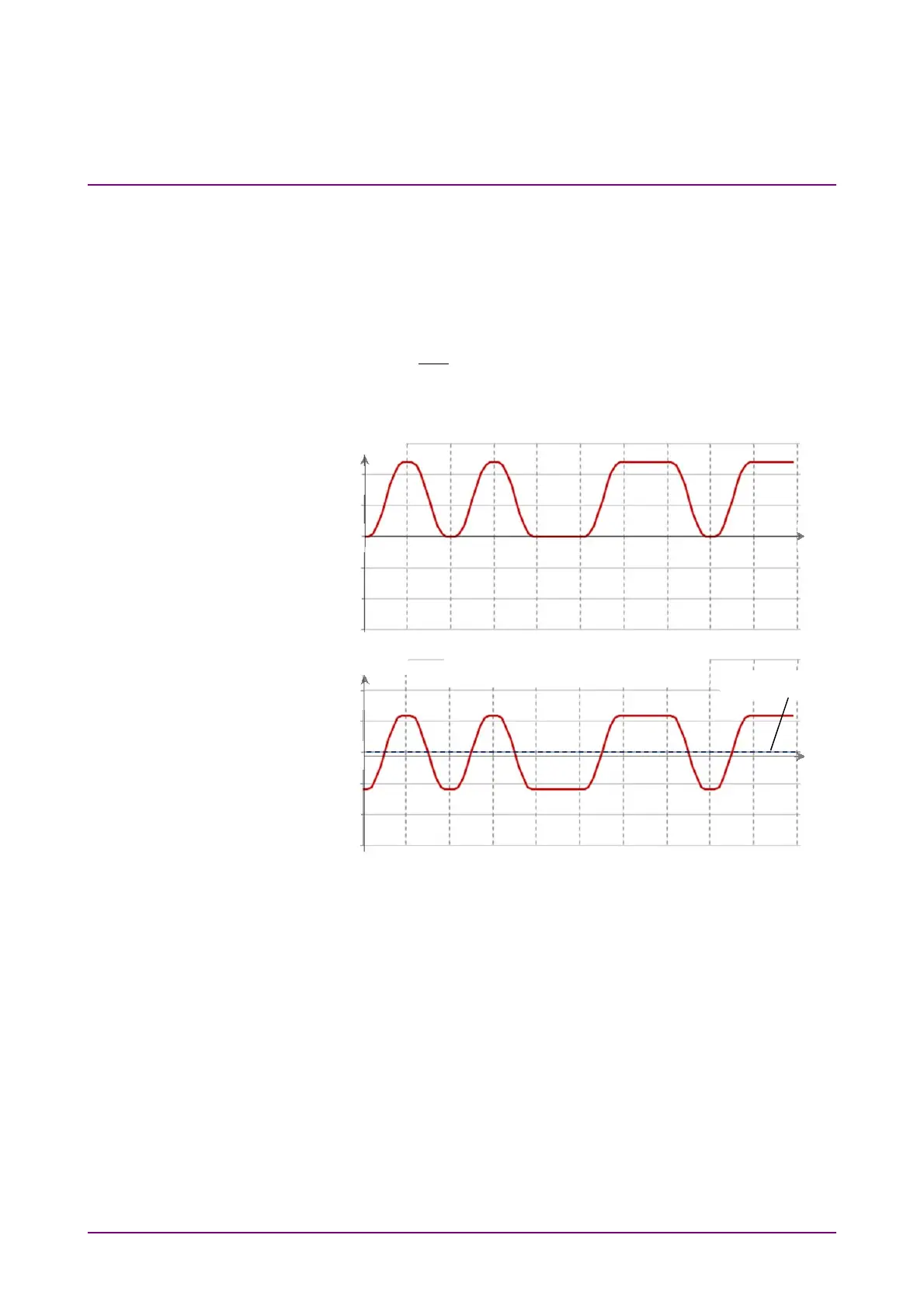
The input connectors are AC coupled, so set a voltage corresponding to the
signal waveform excluding the DC components.
The waveform excepting the waveform input to the connector and the DC
component when inputting the 1.2V LVCMOS signal to the
Data In
connector and
Data
In
connector is shown below.
Set the threshold level to the waveform excepting the DC component.
Figure 5.2.8-2 Waveform That Threshold Level Can be Set
Logic
Select the positive logic (POS) or negative logic (NEG).
Voltage (V)
Waveform without DC component
Time
Voltage (V)
Waveform input to Data In–Data
In connectors
Time
0
0
Threshold level
1
1
1
1