5.2 PPG/ED Panel
5-21
5
How to Operate BERT
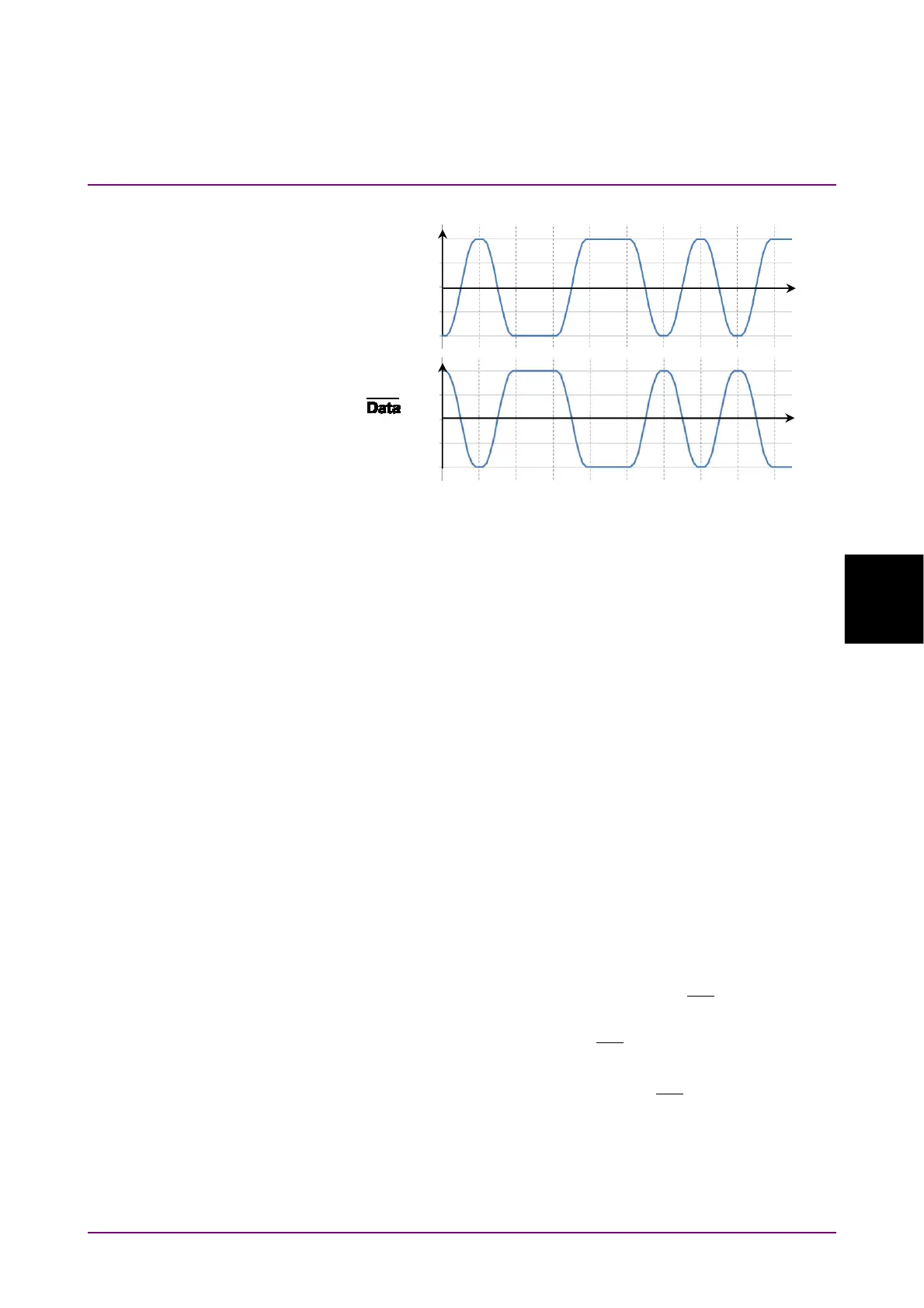
Figure 5.2.8-3 Values Defined as Input Waveform
Pattern
The ED compares the received bit string and the internally generated bit
stream bit-by-bit and evaluates it differences as it errors.
As a result, set the same pattern at the PPG and ED.
The setting procedure of the error detection conditions is as follows:
1. When changing the bit rate and pattern of the PPG and applying the
changing settings to the ED click the Tracking button and set to On.
When setting to On, go to the step 6.
When setting to Off, go to the step 2.
2. Click the Bit Rate button and select the standard.
3. Click the Test Pattern button and select the pattern.
Set the same pattern of the PPG.
4. Set Logic to POS or NEG.
5. Click the ED Input Condition button.
6. Select the connector receiving the signal from the followings:
Differential 50 Ohm:
Data In
and
Data
In
connectors
Electrical Single-Ended Data:
Data In
connector
Electrical Single-Ended XData:
Data
In
connector
7. Click the Ext ATT text box.
8. When inserting the fixed attenuator to the
Data
In
and
Data In
connectors, enter the attenuation (dB). When not inserting the
attenuator, enter 0.
9. Click the Threshold text box.
10. Enter the threshold voltage.
Input waveform
to the
Data In
connector
Input waveform
to the
In
connector
Time
Time
0
0
POS 0 1 0 0 1 1 0 1 0 1
NEG 1 0 1 1 0 0 1 0 1 0
Voltage (V)
Voltage (V)