Chapter 5 How to Operate BERT
5-24
When SYNC Loss is displayed in red
Pattern synchronization has not been obtained; check the following:
The Test Pattern generated by the DUT matches the Test Pattern for
the error detector.
The Logic POS and NEG settings are correct.
A suitable threshold voltage has been set for the signal input to the
Data In
connector and the
Data
In
connector.
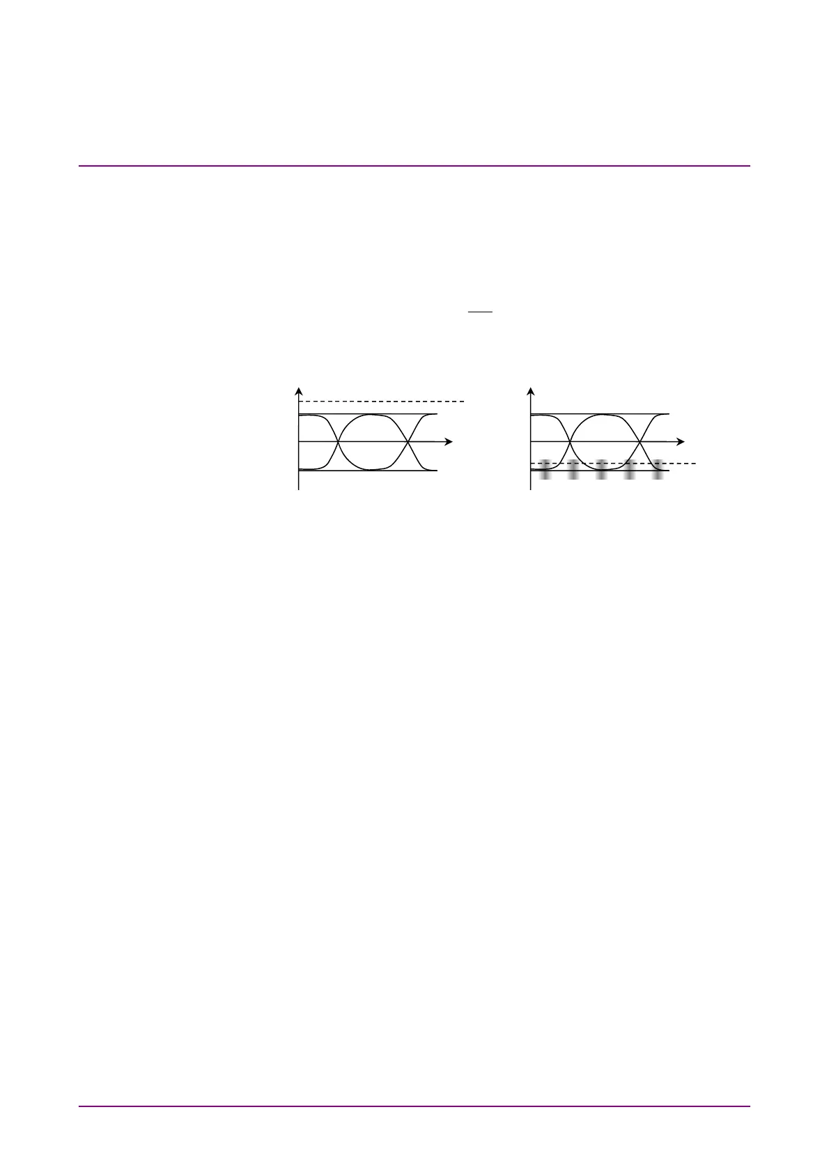
Figure 5.2.9-2 Examples of Improper Thresholds
Threshold is not between level
0 and 1
Excessive noise close to
threshold level
Threshold
Threshold