Chapter 6 How to Operate Sampling Scope
6-8
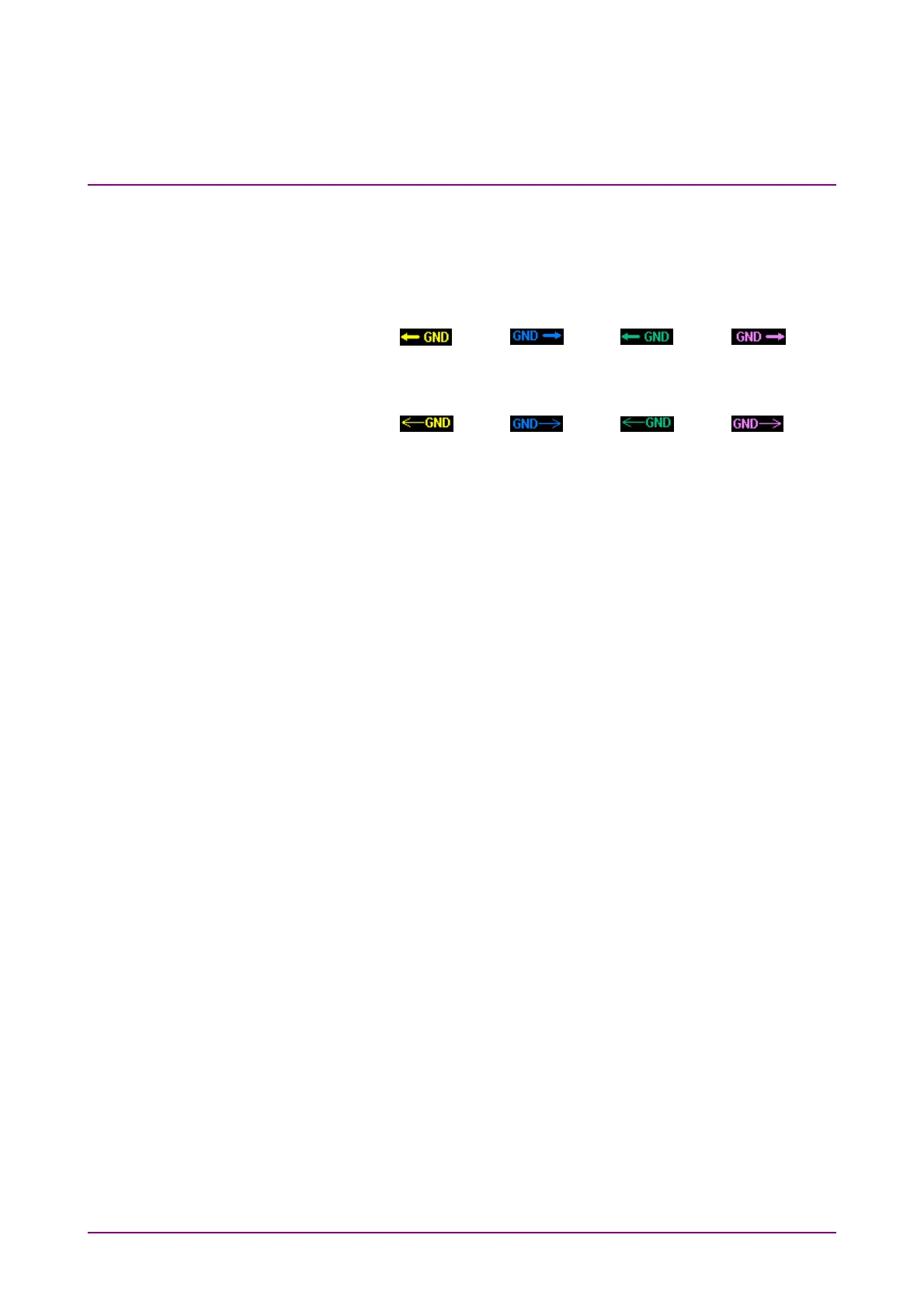
Note:
The arrows that indicate the GND levels appear differently
according to the options installed.
■ With MP2110A-021, 022, 023, 025, 026, 040, 042, 043, 045, 046
or 049, the GND levels are indicated by thick lines.
Ch A: Ch B: Ch C: Ch D:
■ With MP2110A-030, 032, 033, 035, 036 or 039, the GND levels
are indicated by thin lines.
Ch A: Ch B: Ch C: Ch D:
Depending on the type of input signal, you may receive a warning
in the waveform display area. In this case, connect an attenuator to
the optical connector to lower the input level.
Overload: The waveform is distorted because the optical input
power exceeds the upper limit.
An index of the peak power level is 2200 µW for SM
(2600 µW for MP2110A-x30 and x40) and 3200 µW for
MM.
Clipped: A clipped waveform is displayed because the amplitude
of the electrical input signal (for optical input,
O/E-converted signal) exceeds the dynamic range. An
index of the dynamic range is ±400 mV.
Quick Menu
Provides the setting items frequently used.
For how to adjust scale and offset, refer to 6.8, “Adjusting Scales”,
Amplitude:
Sets the scale and offset of the vertical axis.
Time:
Sets the scale and offset of the horizontal axis.
When Sampling Mode is Pulse, Offset is displayed.
Otherwise, Delay is displayed.
Waveform:
Sets the button color of the active channel.
When, in the Setup Dialog Box, Waveform is set to Gray Scale, the
color of the trace graph changes as well.