6.2 Explanation of Windows
6-7
6
How to Operate Sampling Scope
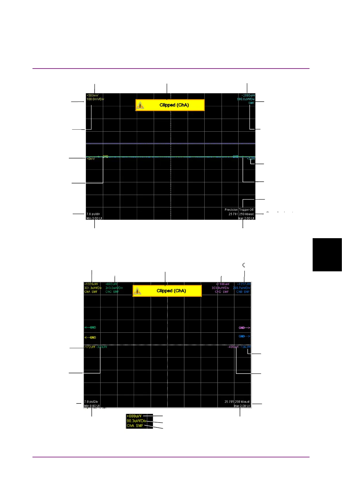
Figure 6.2.1-5 Waveform display area
Figure 6.2.1-6 Waveform display area
(MP2110A-030, MP2110A-039, MP2110A-040, and MP2110A-049)
S
mbol rate
Time offset
Channel B
Level scale
Channel B
Level offset
Channel A Top level
Channel A
Level offset
Time at right edge of display area
Channel A
Level scale
Channel B Top level
Time scale
Channel A
GND level
Channel B
GND level
Precision
trigger status
Channel B
Optical
connector type
Channel A
Optical
connector type
On-screen warning
Symbol rate
Time offset
Channel B
Level offset
Channel A information
Channel A
Level offset
Time at right edge of display area
Channel B information
Time scale
Channel C
Level offset
Channel D
Level offset
On-screen warning
Channel C
information
Channel D
information
Top level
Level scale
O
tical connector