Chapter 6 How to Operate Sampling Scope
6-78
adjusted to the active channel signal.
● When Control Ch is All
The time axis offset is adjusted to the active channel signal. The
Software Delay settings for channels other than the active
channel are also adjusted so that the waveforms are displayed
in the center.
The amplitude axis scale and offset are adjusted to all channel
signals.
In addition to the scale adjustment of waveform display area, Auto
Scale automatically detects the division rate of the data rate of
input signal and the trigger signal. Set Divide Ratio Detect to Off to
not detect the division rate automatically. When Tracking of Data
Rate and Clock Rate is set to On, the division rate of the data rate
and the trigger signal is not detected.
For Pulse Mode
1. Click Auto Scale.
2. The waveform is displayed at the screen center.
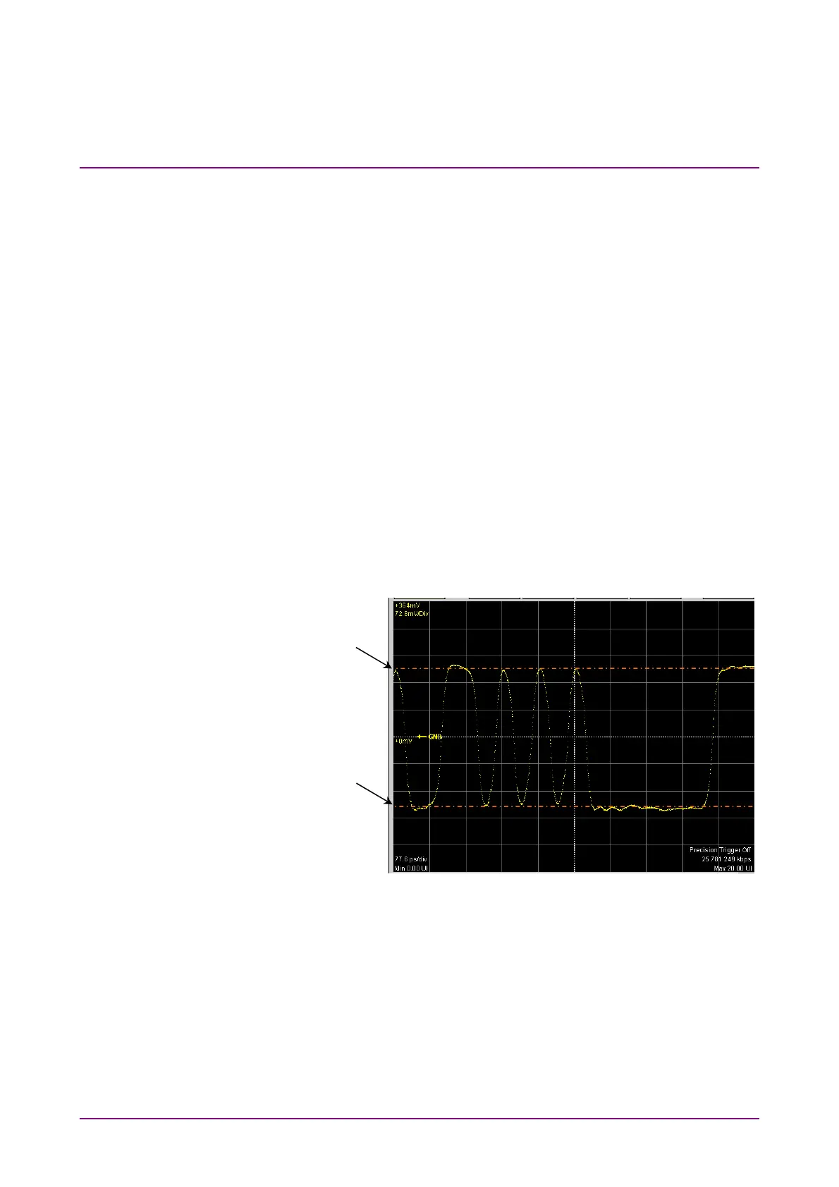
Figure 6.8.1-2 Waveform Display after Auto Scale (Pulse Mode, NRZ)
When the pattern length is 127 bits or less, a 20-bit waveform is displayed.
When the pattern length is 128 bits or more, a 50-bit waveform is
displayed.
The One level is adjusted on the vertical scale to the 2.5th scale up from
the screen center and the Zero level is adjusted to the 2.5th scale down
from the screen center.
One level position
Zero level position