Chapter 6 How to Operate Sampling Scope
6-102
Clicking Center moves the marker without depending on the waveforms.
In this case, the setting values of X1, ΔX, Y1, and ΔY are initialized.
Although the marker is not displayed at Display Off, the marker position
can be adjusted by changing the value in the text box.
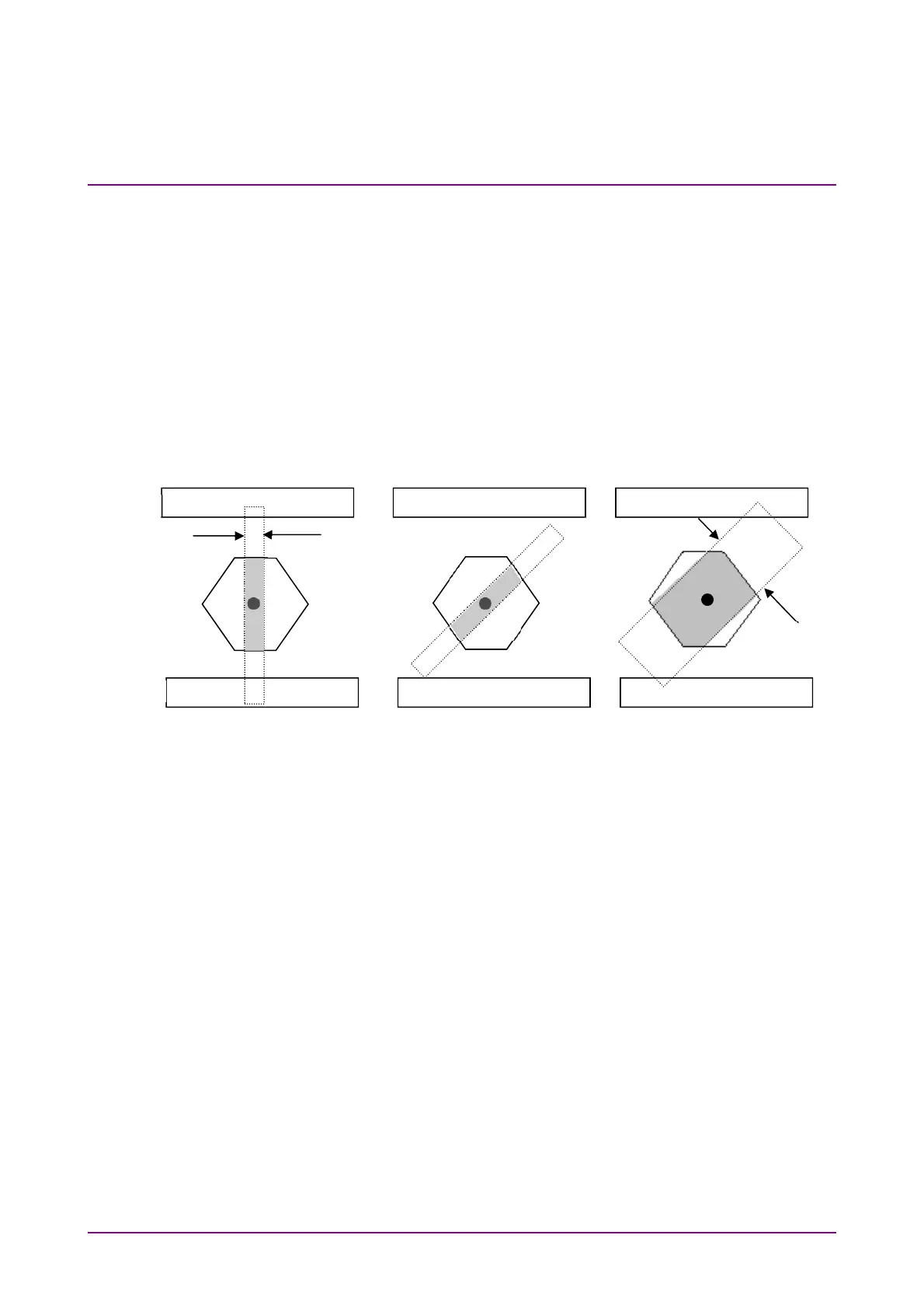
To limit mask area
To examine in which part of the mask at the center the error occurs when
the error occurs in the mask test, the mask area can be limited.
Setting width and angle can limit the mask area.
If the mask area is limited, the error that occurs in an upper and lower
mask area is not measured.
Figure 6.9.2-4 Example of Limiting Mask Area
1. Click Measure.
2. Click Mask Test tab
3 Click the Target Channel button to set the channel.
4. Click the Mask Area Restriction button to set On.
5. Click the Angle text box to set the angle within the range of –90 to
90.
6. Click the Width text box to set the width within the range of 0.01 to
1.00.
Top
Bottom
Center
Angle 0
˚
Width 0.1 UI
Angle 45
˚
Width 0.1 UI
Angle 45˚
Width 0.3 UI
0.1 UI
0.3 UI