Chapter 1 Outline
1-4
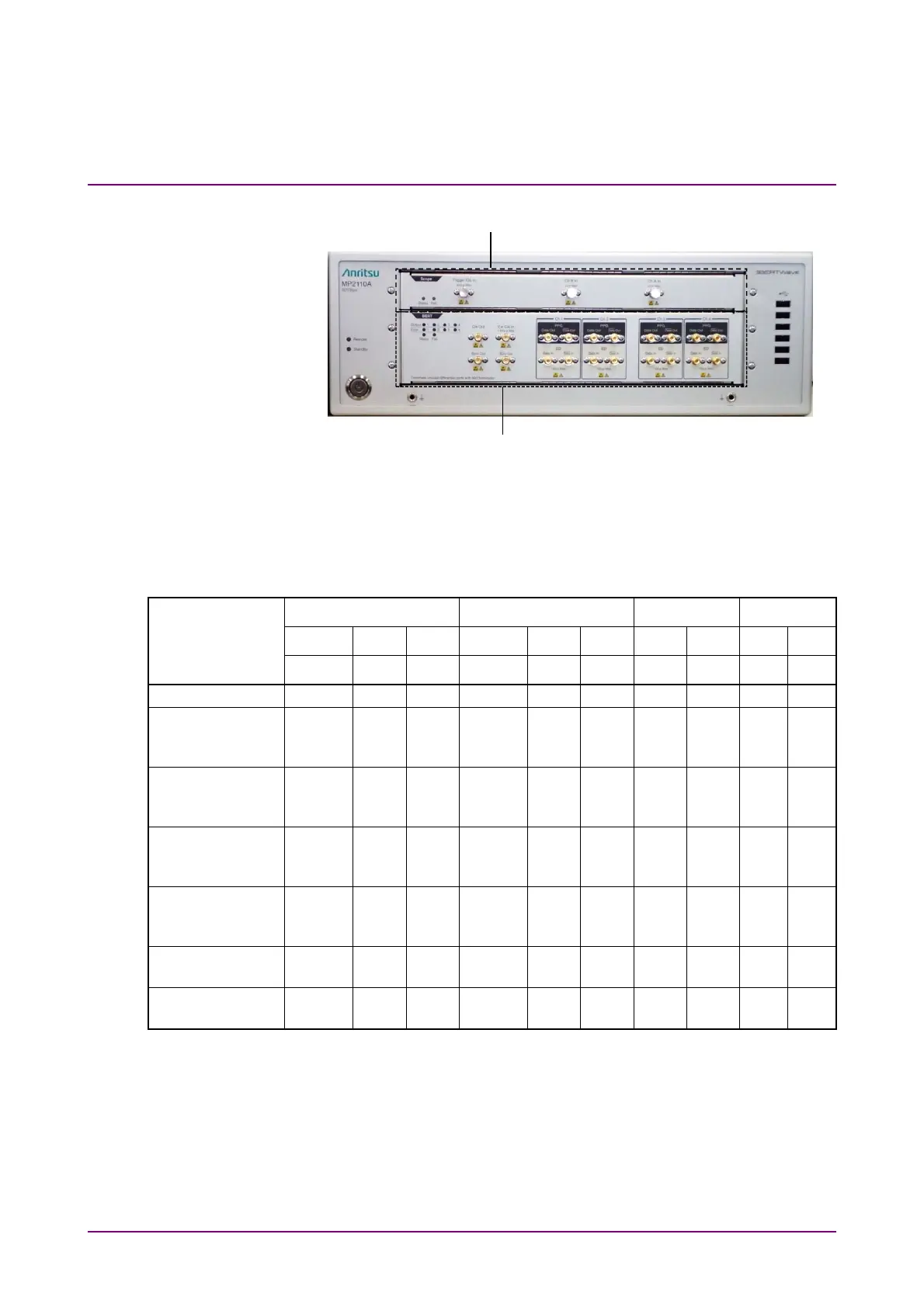
Figure 1.1.1-2 Front Panel of MP2110A
The input connectors of the sampling oscilloscope can be selected by
specifying the option.
Table 1.1.1-1 Sampling Oscilloscope Input Connectors
Channel A Channel B Channel C Channel D
Options Number
Electrical Optical Optical Electrical Optical Optical Optical Optical OpticalOptical
K MMF*
1
SMF*
2
K MMF*
1
SMF*
2
MMF*
1
SMF*
2
MMF*
1
SMF*
2
MP2110A-021
MP2110A-022,
MP2110A-032,
MP2110A-042
MP2110A-023,
MP2110A-033,
MP2110A-043
MP2110A-025,
MP2110A-035,
MP2110A-045
MP2110A-026,
MP2110A-036,
MP2110A-046
MP2110A-030,
MP2110A-040
MP2110A-039,
MP2110A-049
*1: For a multi-mode fiber
*2: For a single-mode fiber
Note:
MP2110A-022, 023, 025, 026, 040, 042, 043, 045, 046, 049 and
MP2110A-030, 032, 033, 035, 036, 039 have different reference
receiver properties (Bessel filter approximation property) of optical
channel. MP2110A-030, 032, 033, 035, 036, and 039 are adjusted to
have flat baseband properties.
BERT: Bit Error Rate Tester
Scope: Sampling Oscilloscope