7.2 Performance Test for Error Detector
7-15
7
Performance Test
(3) Procedure
1. Connect the
Clk Out
connector and the
Trigger Clk In
connector
of the sampling oscilloscope using a coaxial cable.
2. Connect the coaxial terminator to the
ED1
Data
In
connector
and
PPG1
Data
Out
connector.
3. Attach a 20 dB fixed attenuator to the
PPG1 Data Out
connector.
(Refer to (a) in Figure 7.2.2-1.)
4. Connect the 20 dB fixed attenuator and
Ch A In
connector using
a coaxial cable.
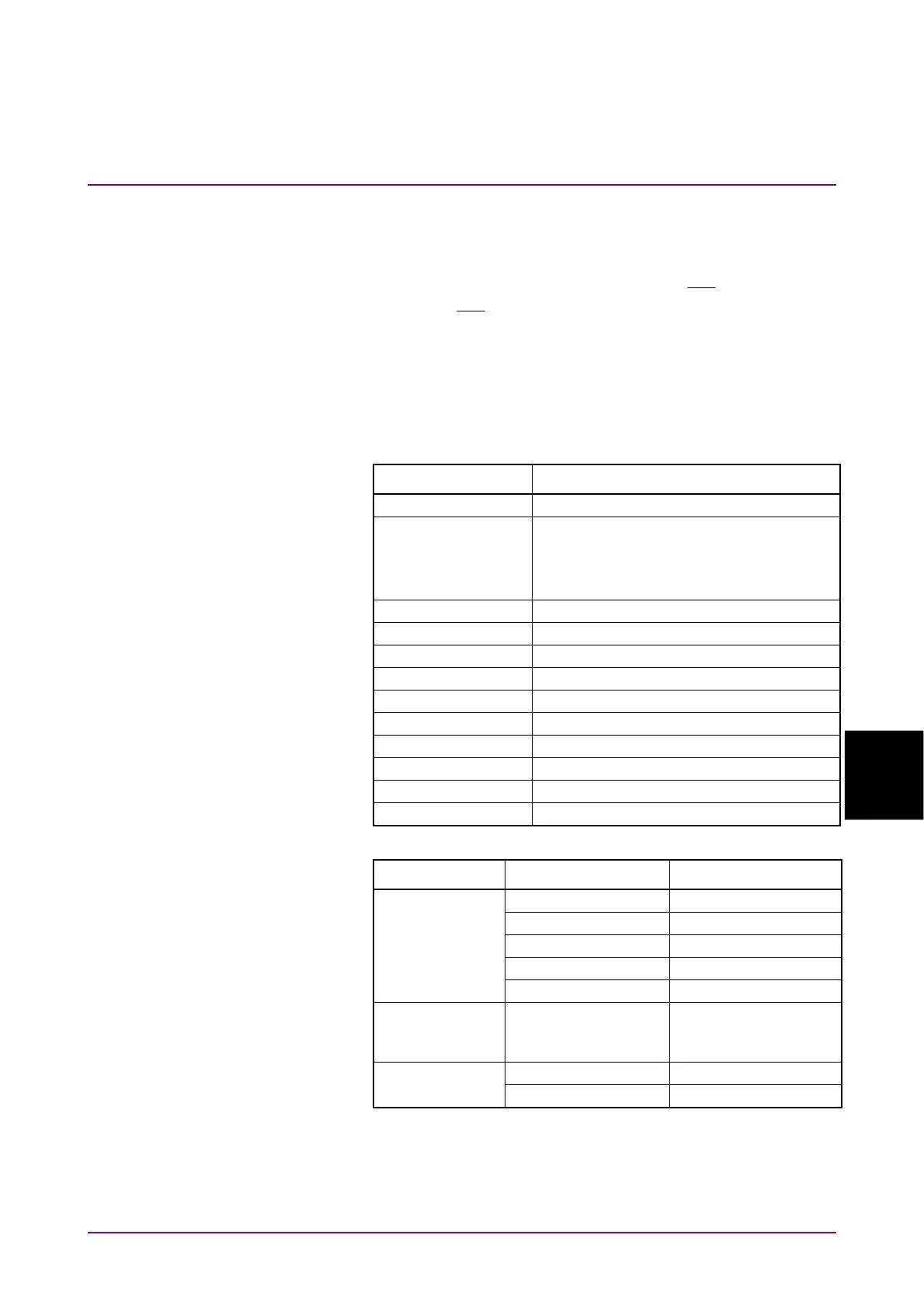
5. Click PPG/ED Ch1. Configure the settings as shown below:
Item Setting Value
Reference Clock Internal
Bit Rate When MP2110A-093 is not installed:
24 300 000 kbit/s, –100 ppm
When MP2110A-093 is installed:
9 500 000 kbit/s, –100 ppm
Clock Output Ch1/2
PPG Amplitude 0.5
External ATT 0
Test Pattern (PPG) PRBS 2^31–1, POS
Test Pattern (ED) PRBS 2^31–1, POS
ED Input Condition Single-Ended Data
Threshold 0 mV
PPG Data/XData ON
Gating Cycle Single
Gating Period 45 s
6. Click Scope. Configure the settings as shown below:
Dialog Box Item Setting Value
Setup Signal Type NRZ
Sampling Mode Eye
Number of Samples 4050
Accumulation Time Persistency
Time 10.0 sec
Time Tracking Symbol Rate: PPG,
Divide Ratio: Clock
Output
Measure - Display On
Amplitude/Time Item Selection (Ch A) Eye Amplitude
7. In the Scope window, click Ch A to measure the amplitude.
8. Adjust the PPG1 Amplitude so that the Scope amplitude is 50±1
mV.