Chapter 7 Performance Test
7-18
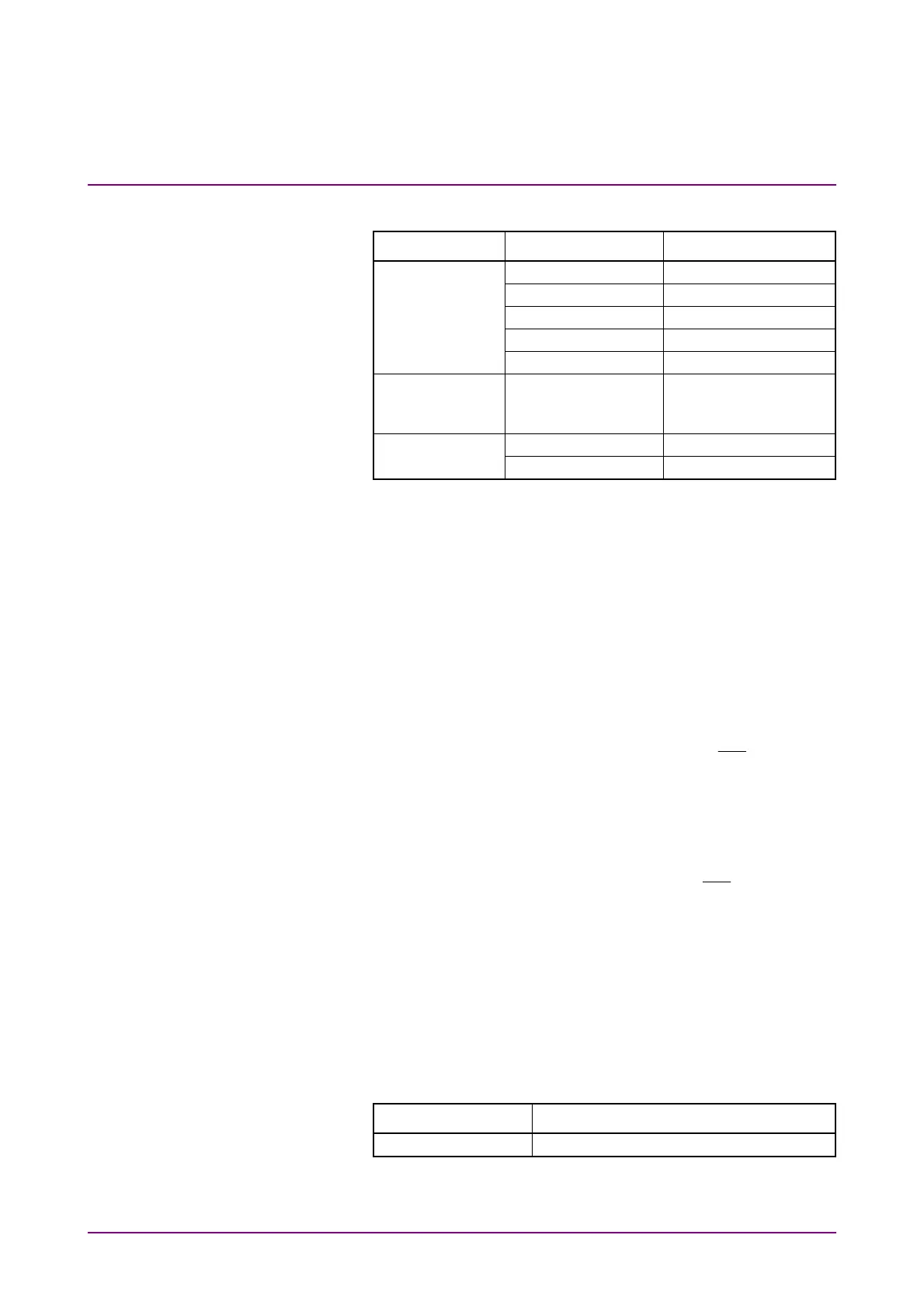
6. Click Scope. Configure the settings as shown below:
Dialog Box Item Setting Value
Setup Signal Type NRZ
Sampling Mode Eye
Number of Samples 4050
Accumulation Time Persistency
Time 10.0 sec
Time Tracking Bit Rate: PPG,
Divide Ratio: Clock
Output
Measure - Display On
Amplitude/Time Item (Ch A) Eye Amplitude
7. In the Scope window, click Ch A to measure the amplitude.
8. Adjust the PPG1 Amplitude so that the Scope EYE amplitude is
40±1 mV.
9. Connect the 20 dB fixed attenuator and
ED1 Data In
connector
using a coaxial cable. (Refer to (b) in Figure 7.2.2-1.)
10. Click Start at All Measurements.
11. Record the error rate ER for the ED Result after measurement is
complete.
12. Connect coaxial terminators to the
PPG1 Data Out
and
ED1
Data In
connectors. (Refer to (a) in Figure 7.2.2-2.)
13. Attach the 20 dB fixed attenuator to the
PPG1
Data
Out
connector.
14. Connect the 20 dB fixed attenuator and
Ch A In
connector using
a coaxial cable.
15. Repeat steps 7 and 8.
16. Connect the 20 dB fixed attenuator and
ED1
Data
In
connector
using a coaxial cable. (Refer to (b) in Figure 7.2.2-2.)
17. Click PPG/ED Ch1.
18. Set ED Input Condition to Single-Ended XData.
19. Repeat steps 10 and 11.
For ED2 to ED4, perform tests in the same way. For ED3 and ED4 test,
change the Clock Output in step 4 to the following value.
Item Setting Value
Clock Output Ch3/4