Chapter 7 Performance Test
7-32
(3) Procedure
The SMF performance test for Ch B is explained below.
1. In case of Figure 7.3.3-1, connect the
Sync Out
connector and
the
Trigger Clk In
connector using a coaxial cable.
In case of Figure 7.3.3-2, connect the
Trigger Clk In
connector
and the signal generator
output
connector using a coaxial cable.
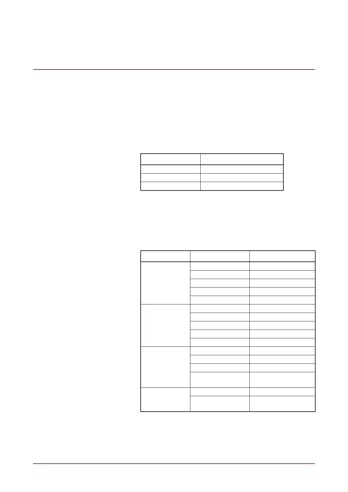
2. In case of Figure 7.3.3-1, click PPG/ED Ch1. Configure the
settings as shown below:
Item Setting Value
Reference Clock Internal
Bit Rate Variable, 28 Gbit/s, 0 ppm
Sync Output PPG_1/8 Clk
In case of Figure 7.3.3-2, set the signal generator as follows:
Frequency: 3.5 GHz
Amplitude: 0.5 Vp-p (at sine-wave –2.0 dBm)
3. Confirm that no light has been input to the optical connector
(SMF or MMF) for
Ch B In
.
4. Click Scope. Configure the settings as shown below:
Dialog Box Item Setting Value
Setup Signal Type NRZ
Sampling Mode Eye
Number of Samples 2048
Accumulation Time Persistency
Limit Type 10.0 sec
Time Tracking Off
Divide Ratio 8
Unit UI
UI On Screen 2
Software Delay 0
Amplitude Ch B Scale 20
W/Div.
Ch B Offset 60
W
Ch B Attenuation 0 dB
Input Connector
(Wavelength)
SMF 1310 nm
Measure - Display On
Amplitude/Time Item (Ch B) Average Power
(dBm)
5. Click Calibrate Module of Amplitude. Click OK after completing
the calibration.
6. Prepare the variable optical attenuator for single-mode fiber.





 To Next Page