Chapter 7 Performance Test
7-34
The MMF performance test for Ch B is explained below.
1. In case of Figure 7.3.3-1, connect the
Sync Out
connector and
the
Trigger Clk In
connector using a coaxial cable.
In case of Figure 7.3.3-2, connect the
Trigger Clk In
connector
and the signal generator
Output
connector using a coaxial cable.
2. In case of Figure 7.3.3-1, click PPG/ED Ch1. Configure the
settings as shown below:
Item Setting Value
Reference Clock Internal
Bit Rate Variable, 28 Gbit/s, 0 ppm
Sync Output PPG_1/8 Clk
In case of Figure 7.3.3-2, set the signal generator as follows:
Frequency: 3.5 GHz
Amplitude: 0.5 Vp-p (at sine-wave –2.0 dBm)
3. Confirm that no light has been input to the optical connector
(SMF or MMF) for
Ch B In
.
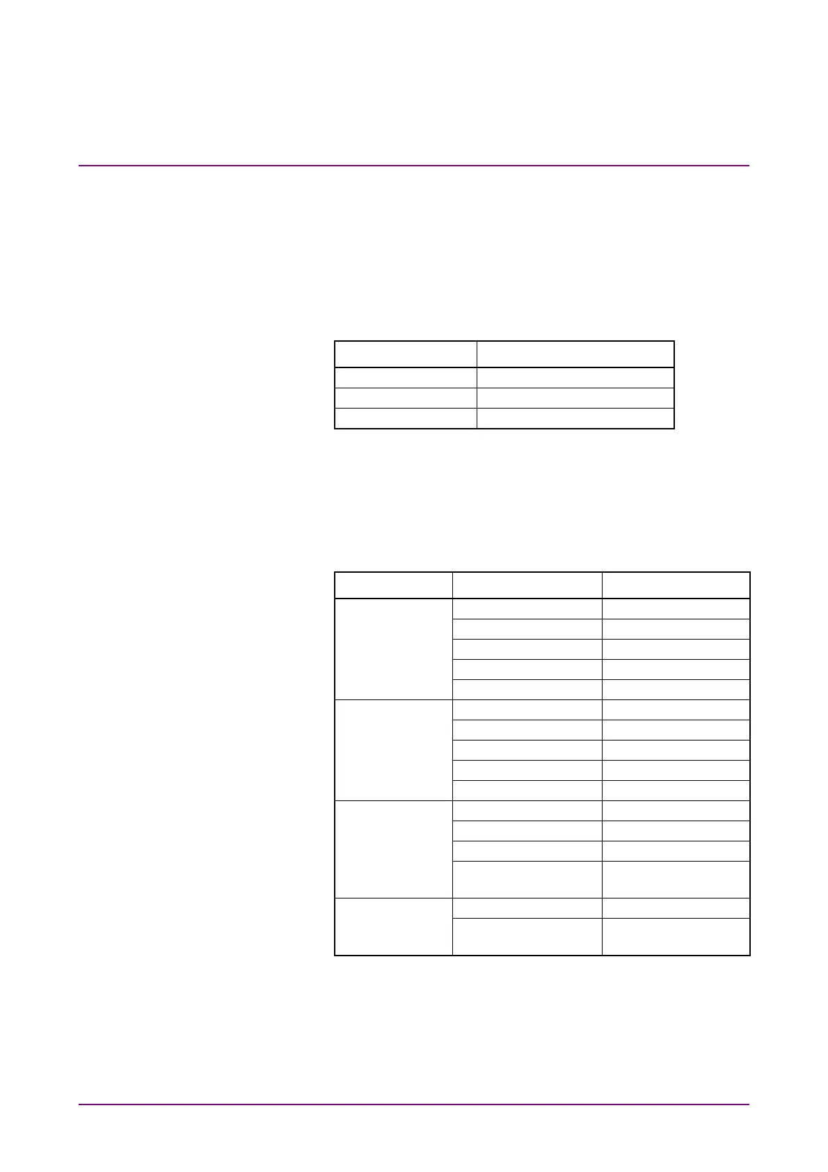
4. Click Scope. Configure the settings as shown below:
Dialog Box Item Setting Value
Setup Signal Type NRZ
Sampling Mode Eye
Number of Samples 2048
Accumulation Time Persistency
Limit Type 10.0 sec
Time Tracking Off
Divide Ratio 8
Unit UI
UI On Screen 2
Software Delay 0
Amplitude Ch B Scale 50
W/Div.
Ch B Offset 150
W
Ch B Attenuation 0 dB
Input Connector
(Wavelength)
MMF 850 nm
Measure - Display On
Amplitude/Time Item (Ch B) Average
Power (dBm)
5. Click Calibrate Module of Amplitude. Click OK after completing
the calibration.
6. Prepare the variable optical attenuator for multimode fiber.
7. Connect the output connector of the light source and the input
connector of the programmable optical attenuator, using a
multi-mode optical fiber.