Chapter 7 Performance Test
7-38
(3) Procedure
Sensitivity Test
1. Connect the
Clk Out
connector and the
Trigger Clk In
connector
of the sampling oscilloscope using a coaxial cable.
2. Connect the coaxial terminator to the
PPG1
Data
Out
connector.
3. Connect an Open connectors to
ED1 Data In
connector, and
ED1
Data
In
connector respectively.
4. Connect a 20 dB fixed attenuator to
PPG1 Data Out
connector.
Refer to Figure 7.3.4-1 (a).
5. Connect the 20 dB fixed attenuator and
Ch A In
connector using
a coaxial cable.
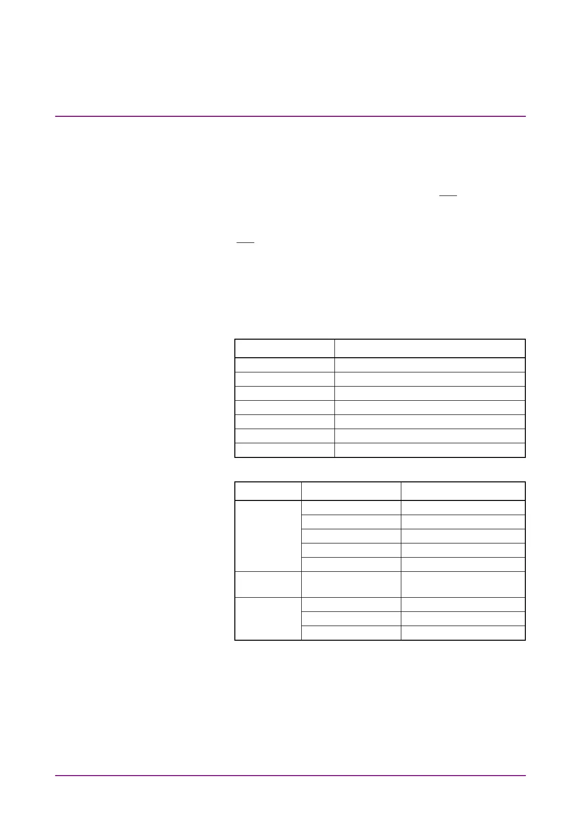
6. Click PPG/ED Ch1. Configure the settings as shown below:
Item Setting Value
Reference Clock Internal
Bit Rate 25781250 kbit/s
Clock Output Ch1/2
PPG Amplitude 0.2
External ATT 0
Test Pattern (PPG) PRBS 2^31–1, POS
PPG Data/XData ON
7. Click Scope. Configure the settings as shown below:
Dialog Box Item Setting Value
Setup Signal Type NRZ
Sampling Mode Eye
Number of Samples 4050
Accumulation Time Persistency
Time 10.0 sec
Time - Rate Tracking Symbol Rate: PPG,
Divide Ratio: Clock Output
Time - CRU Operation Mode Recovery
Operation Rate 100GbE/4 (25.78125G)
CRU Loop BW 10 MHz
8. Click Ch A of Scope and measure the amplitude.
9. Adjust PPG Amplitude to make the eye amplitude on Scope 20±1
mV.
10. Connect the 20 dB fixed attenuator and
CRU In
connector using
the coaxial cable. Refer to Figure 7.3.4-1 (b).
11. Click Time CRU of Scope and click the CRU tab.
12. Confirm Lock Status turning to Lock in green.