7.3 Performance Test for Sampling Oscilloscope
7-39
7
Performance Test
Additive Jitter Test
1. Remove the 20 dB fixed attenuator from
PPG1 Data Out
connector. Refer to Figure 7.3.4-2 (a).
2. Connect a coaxial terminator to
PPG1 Data Out
connector.
3. Connect the
Sync Out
connector and the
Trigger Clk In
connector using a coaxial cable.
4. Connect the Clk Out connector and the
Ch A In
connector o using
a coaxial cable.
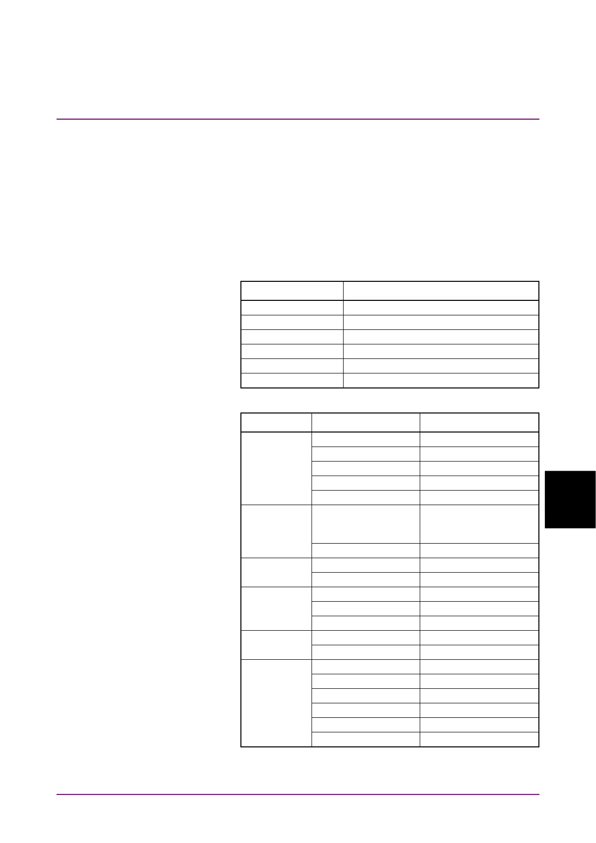
5. Click PPG/ED Ch1. Configure the settings as shown below:
Item Setting Value
Reference Clock Internal
Bit Rate 25781250 kbit/s
Sync Out PPG1_1/8Clk
Clk Out Ch1/2
Test Pattern (PPG) PRBS2^31–1
PPG Data/XData ON
6. Click Scope. Configure the settings as shown below:
Dialog Box Item Setting Value
Setup Signal Type NRZ
Sampling Mode Eye
Number of Samples 4050
Accumulation Time Persistency
Time 10.0 sec
Time - Rate Tracking Symbol Rate: PPG,
Divide Ratio:
UserDefined
Divide Ratio 4
Time - Unit UI
Scale/Offset UI on Screen 1 UI
Time - CRU Operation Mode Recovery
Operation Rate 100GbE/4 (25.78125G)
CRU Loop BW 10 MHz
Amplitude Scale 10.0 mV/Div
Offset 0 mV
Histogram Histogram On
Axis Time
X1 0.00 UI
X2 1.00 UI
Y1 1 mV
Y2 –1 mV
 Loading...


