2.2 Part Names
2-11
2
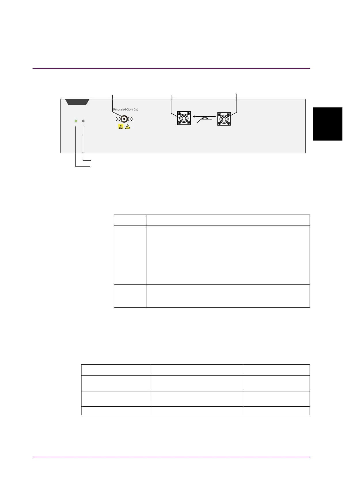
CRU Panel
Figure 2.2.1-9 CRU Panel Names (MP2110A-055)
The following tables describe the panel.
Table 2.2.1-6 Lamp List
Name Description
Lights when MP2110A can receive remote commands upon
successful start. The color indicates the clock recovery
status.
Green: The clock is recovered normally.
Red: The input signal is not detected. Check that the
signal is input to the
Data In
connector.
Orange: The input signal is detected but is out of the
Lights in red when a hardware error is detected at startup.
The lamp may light in short time when turning on and off
the power, but this is not an error.
*: Check the following item when the Status lamp is lit in orange. Refer
to Section 6.2.6, “Time, CRU Dialog Box”, for the operation method.
•
Set the operation rate according to the signal input to the
Optical
SMF Data In
connector.
Table 2.2.1-7 Connector List
Connector Name Description Maximum Input Level
Clock recovery unit optical input
Range: 1260 to 1620 nm
Clock recovery unit optical
output
Clock recovery unit output
SMF