Chapter 2 Before Use
2-10
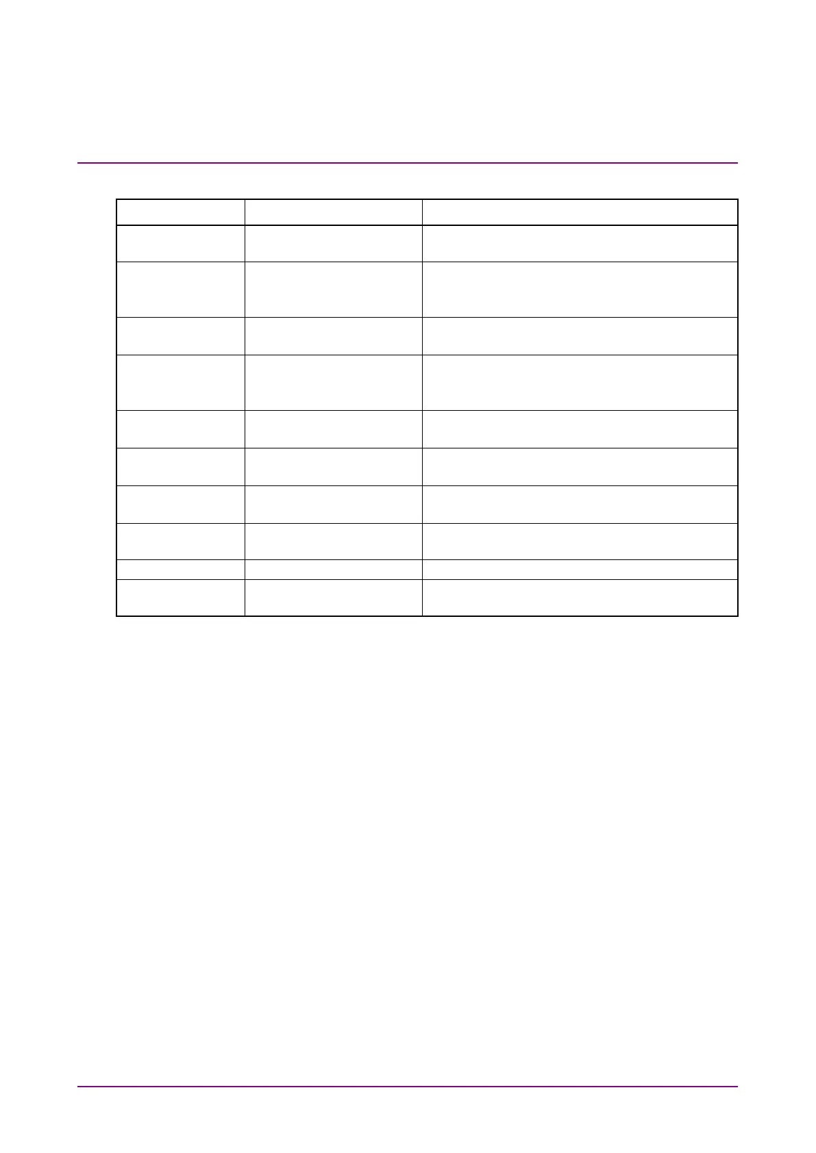
Table 2.2.1-5 Connector List
Connector Name Description Maximum Input Level
For trigger clock input to
the sampling oscilloscope.
1
SMF: 860 to 1650 nm
SMF optical connector: +8 dBm peak
MMF optical connector: +10 dBm peak
2
SMF: 1260 to 1650 nm
MMF: 800 to 860 nm
SMF optical connector: +8 dBm peak
MMF optical connector: +10 dBm peak
1
SMF: 860 to 1650 nm
SMF optical connector: +8 dBm peak
MMF optical connector: +10 dBm peak
SMF: 1260 to 1650 nm
MMF: 800 to 860 nm
SMF optical connector: +8 dBm peak
MMF optical connector: +10 dBm peak
2
SMF: 1260 to 1650 nm
MMF: 800 to 860 nm
SMF optical connector: +8 dBm peak
MMF optical connector: +10 dBm peak
SMF: 1260 to 1650 nm
MMF: 800 to 860 nm
SMF optical connector: +8 dBm peak
MMF optical connector: +10 dBm peak
3,
4
Clock recovery unit input
3
Clock recovery unit
output
*1: When MP2110A-021, 022, 023, 025, 026, 032, 033, 035, 036, 042, 043,
045, or 046 is installed.
*2: When MP2110A-030, 039, 040, or 049 is installed.
*3: When MP2110A-054 is installed.
*4: When MP2110A-022, 023, 025, 026, 030, 032, 033, 035, 036, 039, 040,
042, 043, 045, 046, or 049 is installed.