7. Lenses & lens holder
1121
11
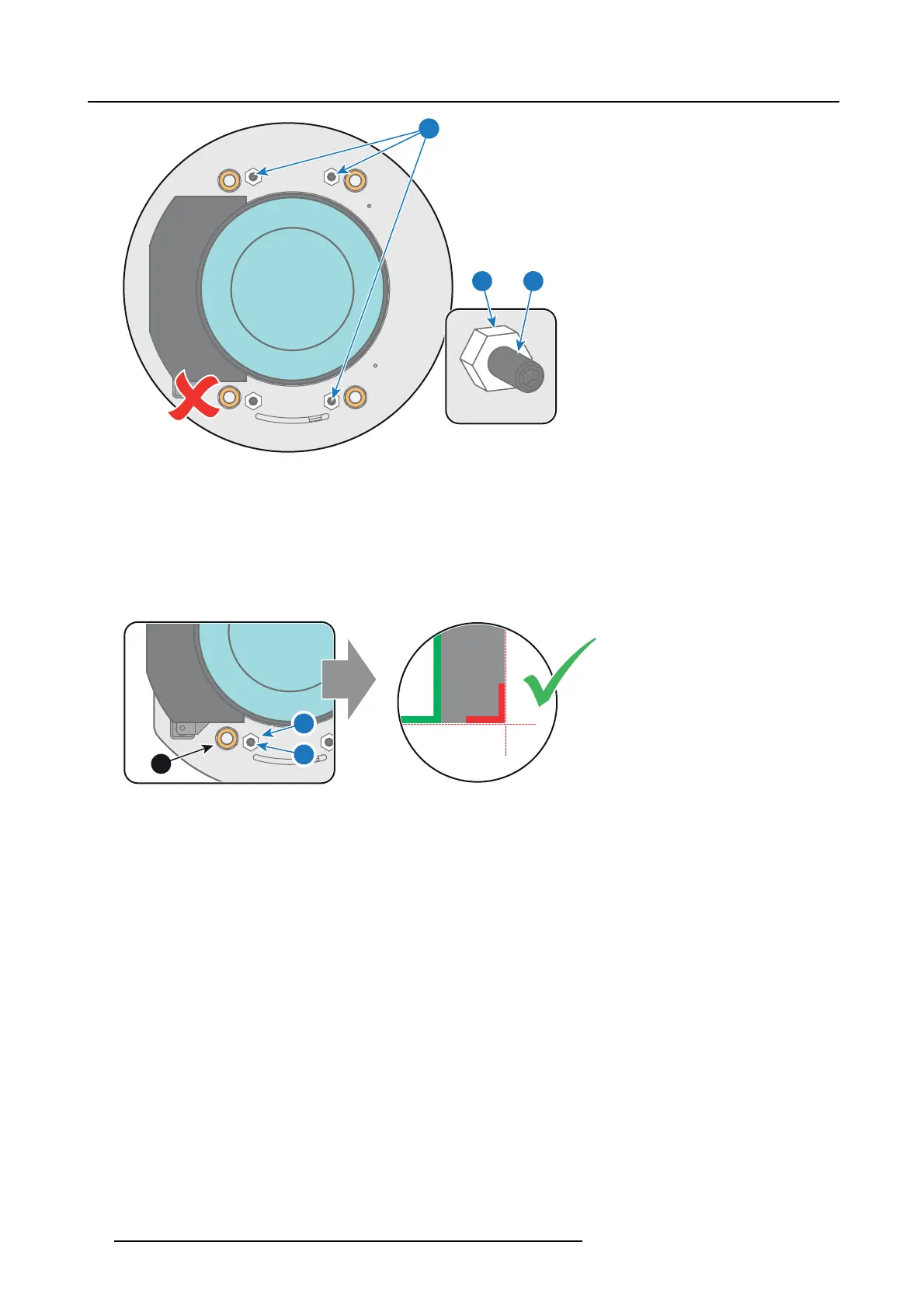
Image 7-37
5. G ently turn (by hand) the S cheimp flug ad justment nut at the lowe
r left of the Lens Holder (reference 4 image 7-38) against the
Lens Holder front plate without disturbing the projected image.
6. Turn in the set screw at the lower left of the Lens Holder (reference 14 image 7-38) without disturbing the projected image . Use
a 3mm Allen wrench.
Note: Ensure that the edges of the projected test pattern r emain in p lace on the screen. Any movem ent of the image will affect
the Scheim pflug adjustment.
Tip: Fasten the set screw and the Scheim pflug nut alternately, without disturbing the projected image, until the Scheimpflug
nut and set screw are completely tightened.
4
14
24
Image 7-38
7. F as ten the loc k nut at the lower left of the Lens Holder. Use a 10mm nut driver.
78
R5906753 DPXK BLP SERIES 20/11/2017