notch on the right side of the housing.
1.1.2 Connectors
The devices have about a 4-port gigabit switch-port, a gigabit LAN/WAN connection, a VD-
SL connection, an ISDN BRI interface, a USB port (type A), as well as a USB console port
(type B).
The connections are arranged as follows:
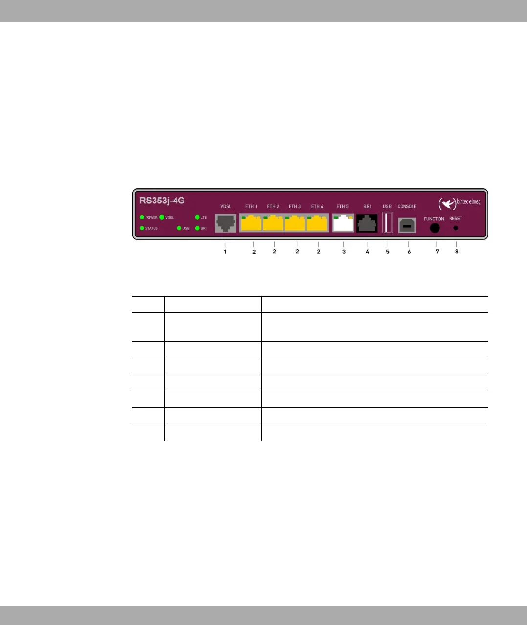
Fig. 2: bintec RS353j-4G front panel
Front panel connections
1 VDSL (gray) VDSL interface
2 ETH1 / ETH2 / ETH3 /
ETH4 (yellow)
10/100/1000 Base-T Ethernet interfaces
3 ETH5 (white) 10/100/1000 Base-T Ethernet interfaces
4 BRI (black) BRI connection
5 USB USB connection type A
6 USB CONSOLE USB console type B
7 FUNCTION Function button
8 RESET Reset button
On the back of the device the mains connection and the on/off switch is located. bintec
RS353j-4G has connectors for two external Wi-Fi antenna. The devices bintec RS353j-4G
have a connectors for the GPS antenna and 2 ports for the LTE/UMTS antenna. The con-
nectors for the LTE/UMTS antenna are located on the sides of the device.
The connections are arranged as follows:
1 Installation bintec elmeg GmbH
4 bintec RS Series