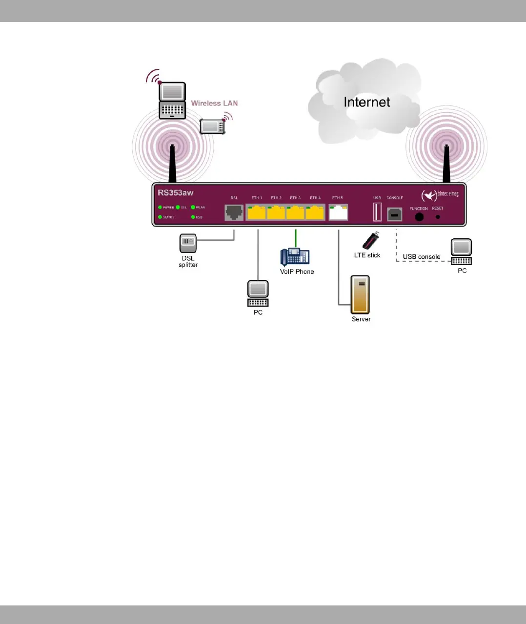
Fig. 5: Connection options using the example of bintec RS353aw
When setting up and connecting, carry out the steps in the following sequence:
(1) Antennas
Screw the external WLAN antennas (only bintec 123w and bintec RS353aw) sup-
plied to the connections provided for this purpose.
(2) ETH1-4
Connect the first switch port (ETH1, yellow connector) your device through the sup-
plied Ethernet cable to your LAN to configure the device. The device automatically
detects whether It is connected to a switch or directly to a PC. Connect more
devices, LANs or WANs to the Port ETH1 up ETH4 on.
(3) DSL (bintec RS353a and bintec RS353aw)
Connect the DSL interface (DSL, grey connector) of your device to the DSL output
of the splitter using the DSL cable (grey cable) supplied.
(4) Power connection
Connect the POWER interface of your device via the supplied power cord to your
power supply.
You can set up further connections as required:
• ETH5
bintec elmeg GmbH
1 Installation
bintec RS Series 11