SECTION 58 - ATTACHMENTS / HEADERS - CHAPTER 1
58-25
Slide the disc hub, 1, onto the top cap shaft; if it
is not perfectly timed to the adjacent discs,
remove the disc hub, rotate it 90° and reinstall it.
Continue to do this until the disc hub is properly
timed; one of the four positions will provide
correct timing.
NOTE: With the adjacent discs positioned at 90
°
,the
breather, 3, should be completely visible through the
disc hub bolt hole, 4, when the hub is properly timed.
After determining the correct position, apply a
thin coating of grease to the seal lip and sealing
surface on disc hub, and carefully slide disc hub
onto shaft past seal. Apply a small amount of
silicone sealant to the end of the disc hub
retaining bolt, 2, and torque it to 224 N⋅m (150
ft-lb).
19986023
1
2
3
4
58
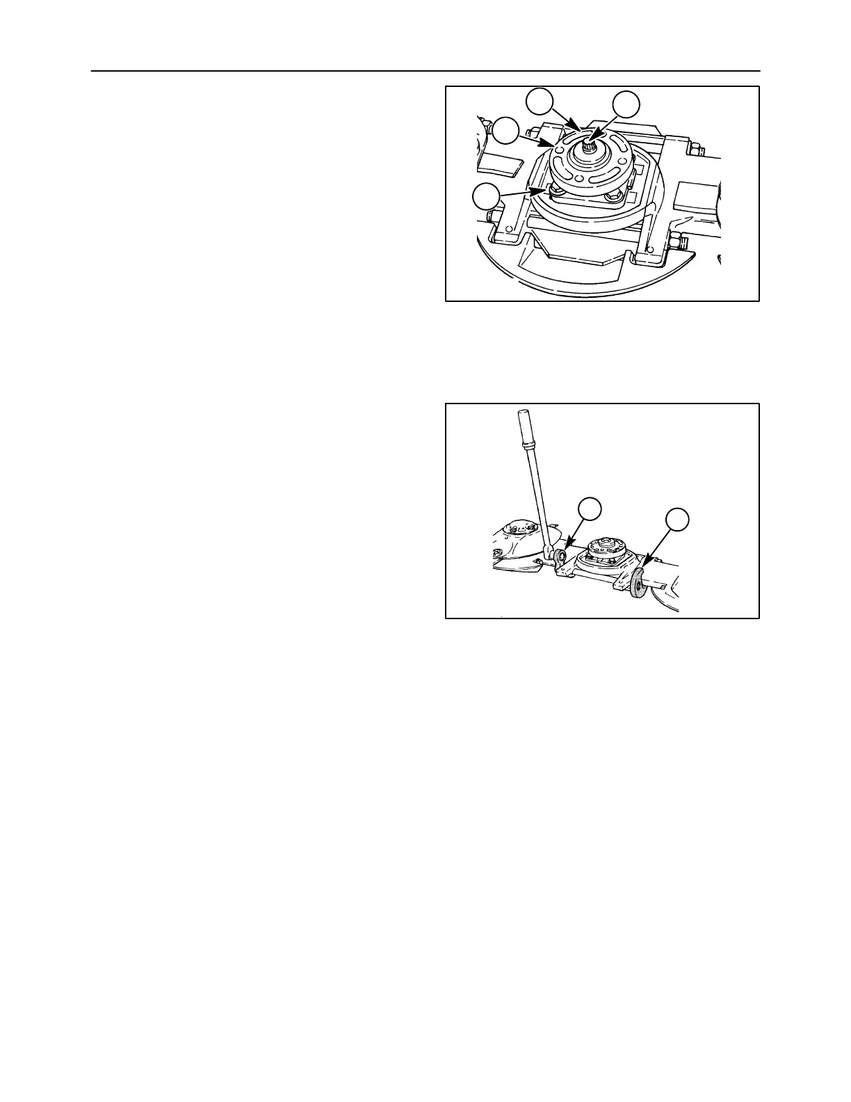
7. The tie bolts which connect the cutter bar
together are torqued using the degree method of
torquing, which requires a special procedure.
Install special holding tools, 1, onto the nuts on
one end of each tie bolt. Then, using special
wrench attachment, 2, with a torque wrench,
tighten both tie bolts to 68 Nám (50 ft-lb).
NOTE: Always torque or turn the rear tie bolt first.
8. Use a marker or scribe to mark the front and rear
nut positions relative to the spacer. Using special
wrench attachment and a 3/4″ breaker bar, turn
each nut 1/2 turn at a time to achieve one full turn
on each tie bolt, starting with the rear tie bolt first.
This will give a total torque on the tie bolt of 68
Nám (50 ft-lb) plus 1 turn, for a clamping force of
15,900 -- 16,800 kg (35,000 -- 37,000 lb).
NOTE: It may be necessary to partially torque the tie
bolts, mount the cutter bar assembly back onto the
unit, and use a cheater bar to obtain enough leverage
to complete tightening the tie bolts.
9. Remove special tools from the cutter bar; it may
be necessary to use a hammer to knock the
special holding tools off of the nuts.
10. Reinstall the rock guard, skid shoe and disc on
the replacement module.
1
2
59