SECTION 58 - ATTACHMENTS / HEADERS - CHAPTER 3
58-14
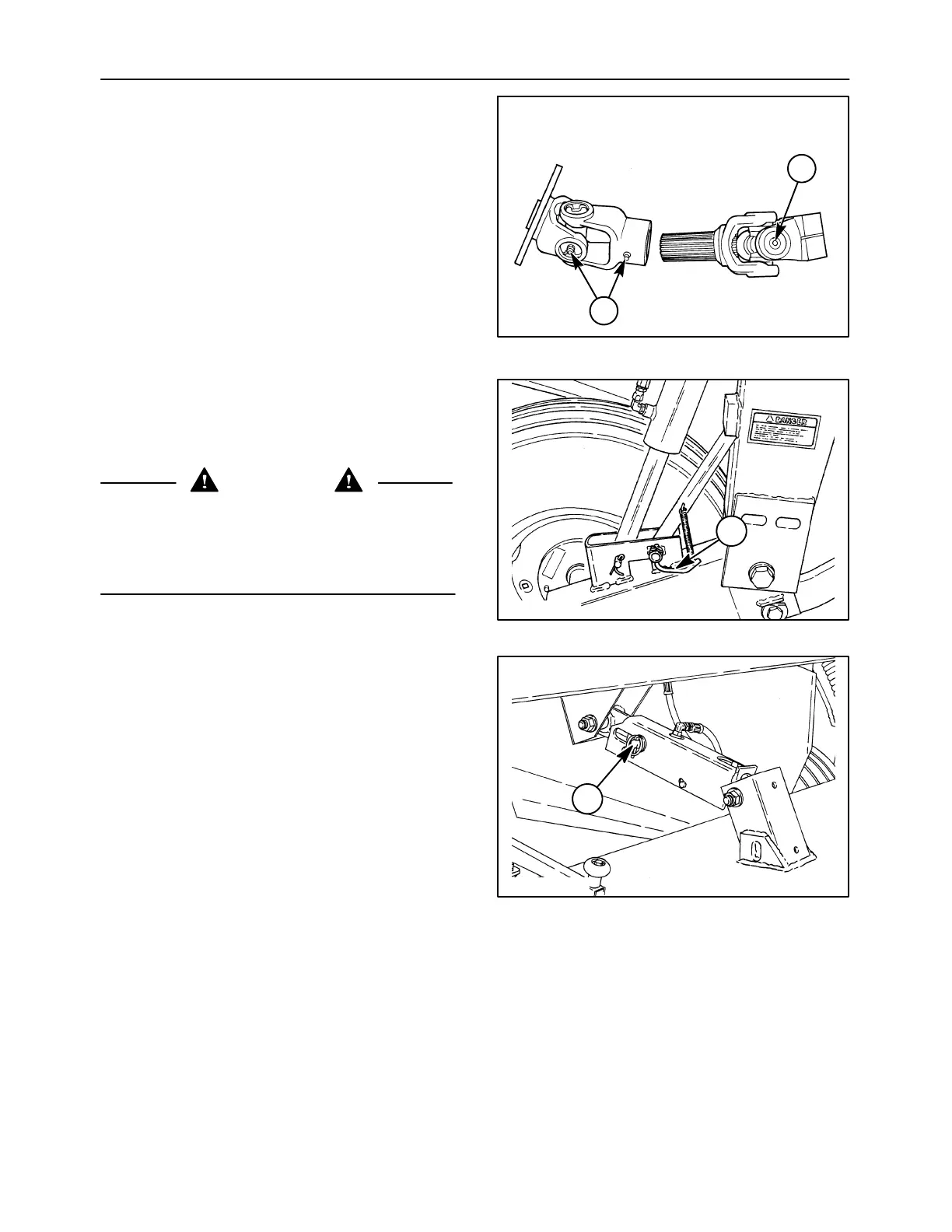
4. Assemble the second yoke repeating steps 1-3.
NOTE: The grease zerk, 1, is oriented to line up with
other grease zerks, 2, on the driveline. Note the
positioning of the bearing for the grease zerk during
reassembly.
5. After complete assembly of the U-joint, strike the
forged surfaces of all yoke ears with a sharp blow
from a hammer. This will ensure proper seating
of the bearings, and eliminate any possible
tightness to ensure a free flexing joint.
IMPORTANT: Use caution not to strike the bearing
bore area of the yoke, as this will damage the bore
and may cause premature cross bearing failure.
1411/8-11
1
2
33
LOWER CONDITIONER ROLL - REMOVAL
1. Raise the header fully and engage the header lift
transport locks by pivoting both right and left lock
levers,1,forward.
DANGER
The header should be resting on the ground or
suspended in the transport position by the
header lift locks during lubrication or mainte-
nance. Failure to comply will result in death or
serious injury.
A3657-29
1
34
2. Install the header tilt cylinder pin, 1, through the
channel slot and the rear hole of the cylinder rod
to lock the header in the level position. Lower the
header onto the transport locks.
19982132
1
35