SECTION 58 - ATTACHMENTS / HEADERS - CHAPTER 3
58-31
Right Side Torsion Arm, Torsion Bar and
Adjusting Tube Disassembly
1. In order to remove the right side roll tension
system components, the left side torsion bar
must be removed. Refer to steps 1 to 4 from “Left
Side Torsion Arm and Bar Disassembly”.
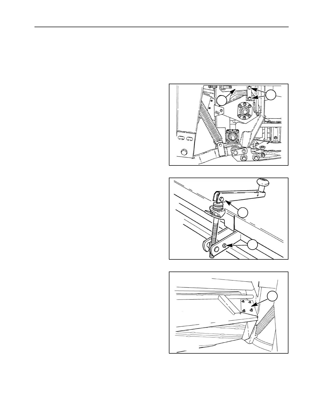
2. Loosen and remove the bolts, 1, and spacers
from the right side roll tension arm straps to the
upper roll pivot arm. Lower the tension arm, 2,
down onto the roll pivot arm.
A5049-3
1
2
82
3. Loosen the bolt and locknut, 1, that pinches the
two mount straps against the adjusting handle
assembly, and remove the handle assembly, 2.
A3659-15
1
2
83
4. To remove the right side roll tension system
components, the swathgate must be removed.
Remove the baffle, 1, at the right end of the
swathgate by removing the four carriage bolts
and nuts.
50012165
1
84