SECTION 58 - ATTACHMENTS / HEADERS - CHAPTER 1
58-20
CUTTER BAR INSTALLATION
1. Support the cutter bar with floor jacks positioned
under each end.
2. Roll the cutter bar under the header, positioning
the attaching arms so that they line up with the
slots in the header frame.
3. Raise the cutter bar with the floor jacks until the
top of the drive shaft is even with the gearbox
output shaft.
50012160
44
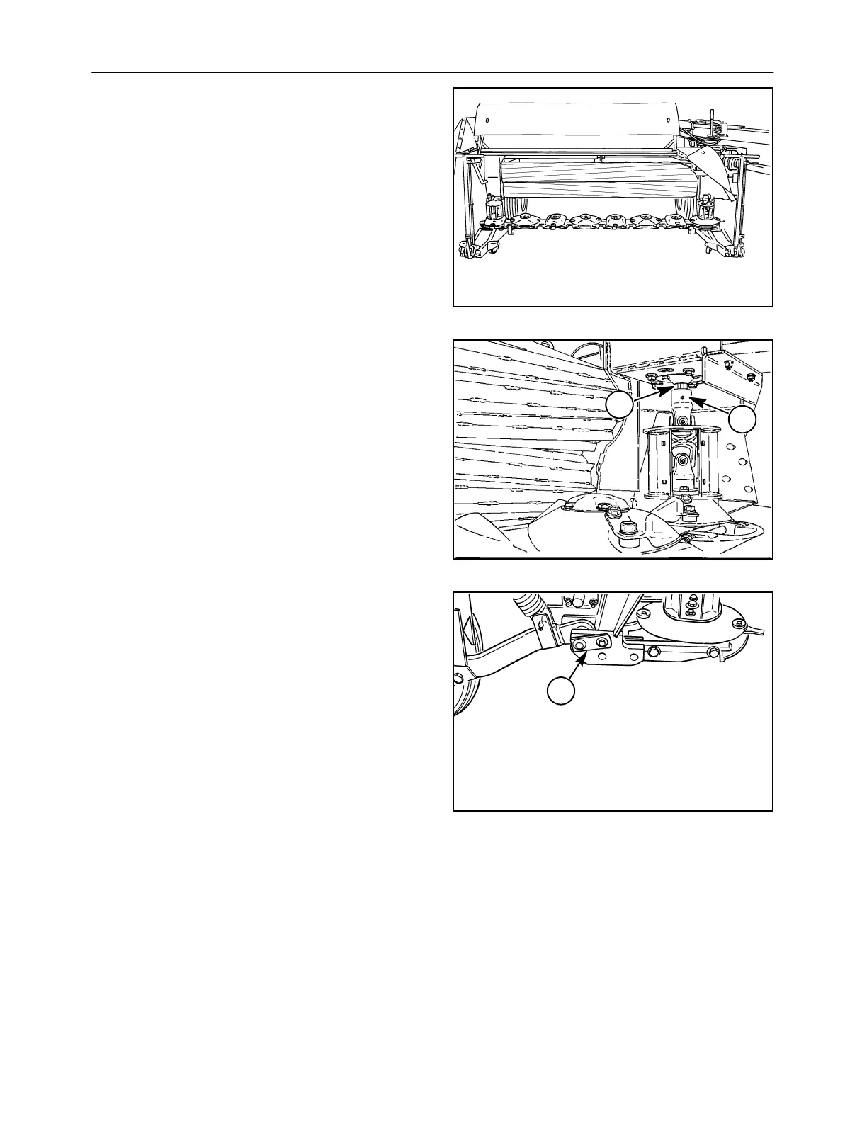
4. Line up the drive shaft splines, 1, with the
gearbox output shaft, 2, and raise the cutter bar
upwards until the attaching arms line up with the
header frame mounts.
20011832
1
2
45
5. Position the cutter bar so that the rear bolts holes,
1, are lined up.
6. Raise or lower the front of the cutter bar as
required to install the front bushings.
7. Install the cutter bar mounting bolt and nut.
Torque the hardware to 271 N⋅m (200 ft-lb).
NOTE: There is a patch of locking compound in the
nut. If the nut is removed for any reason, a new nut
should be installed.
A3658-13
1
46