SECTION 58 - ATTACHMENTS / HEADERS - CHAPTER 2
58-13
BEVEL GEARBOX - INSTALLATION
1. Set the gearbox onto the header frame, inserting
the output shaft through the hole in the frame.
IMPORTANT: The bevel gearbox is heavy and
awkward; use caution not to drop the gearbox as
personal injury or damage to the gearbox may result.
It will be necessary to install the cutter bar drive
shaft over the output shaft of the bevel gearbox
during installation; this can be done in two ways:
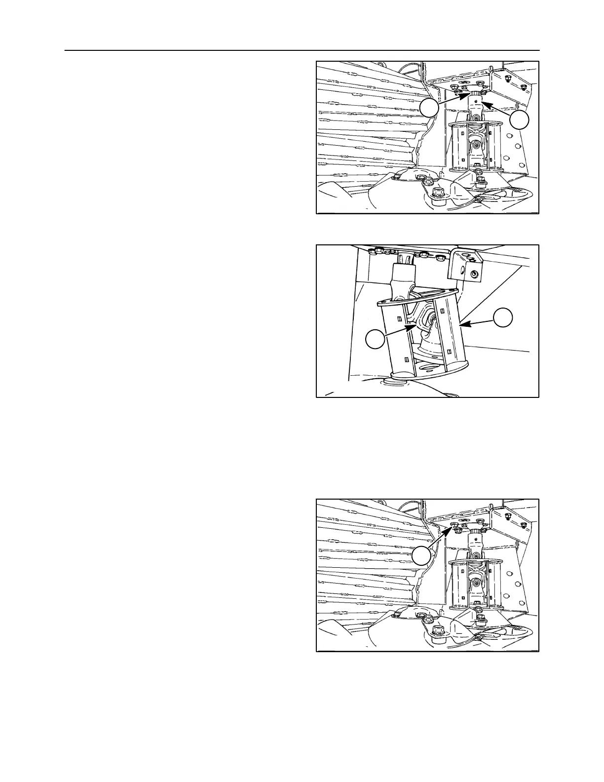
a. While lowering the bevel gearbox onto the
header frame, have a second person align
the cutter bar drive shaft, 1, so that it engages
on the gearbox output shaft, 2.
20011832
1
2
25
b. If gearbox is being installed by one person, it
will be easier to remove the tower, 1, and
drive shaft, 2, by removing the four 1/2″ x
1-3/4″ cap screws and hardened washers. It
will be necessary to remove the wear plates,
if equipped, from the tower to provide
additional clearance when reinstalling the
drive shaft. Install the bevel gearbox onto the
header frame, and reinstall the drive shaft
and tower by sliding the drive shaft up over
the output shaft and position onto the #1 disc.
Ensure the disc is positioned at right angles
to the #2 disc, and torque the four cap screws
to 113 N⋅m (83 ft-lb).
IMPORTANT: Reinstall the correct 1/2
″
x1-3/4
″
cap
screws and hardened washers. Use of incorrect disc
retaining hardware may cause cutter bar lock-up and
potential damage, or may prevent proper retention of
#1 disc.
50011833
1
2
26
2. Install the five cap screws, 1, and flat washers to
retain the gearbox to the header frame, and
torque to 113 N⋅m (83 ft-lb).
20011832
1
27